Class 10 Science Chapter 12 Electricity NCERT Solutions
Before getting into the details of NCERT Solutions For Class 10 Science Chapter 12 Electricity, let’s have an overview of the list of topics and subtopics under Electricity class 10 NCERT solutions:
- Electricity
- Electric Current And Circuit
- Electric Potential And Potential Difference
- Circuit Diagram
- Ohm’S Law
- Factors On Which The Resistance Of A Conductor Depends
- Resistance Of A System Of Resistors
- Heating Effect Of Electric Current
- Electric Power
- विद्युत कक्षा 10 विज्ञान हिंदी में
- Class 10 Electricity Important Questions
- Electricity Class 10 Notes
- Electricity NCERT Exemplar Solutions
- Class 10 Science Electricity Mind Map
NCERT Solutions for Class 10 Science Chapter 12 Intext Questions
Page Number: 200
Question 1
What does an electric circuit mean ?
Answer:
A continuous and closed path along which an electric current flows is called an electric circuit.
Question 2
Define the unit of current.
Answer:
Unit of current is ampere. If one coulomb of charge flows through any section of a conductor in one second then the current through it is said to be one ampere.
I =
Question 3
Calculate the number of electrons constituting one coulomb of charge.
Answer:
Charge on one electron, e = 1.6 x 10⁻¹⁹ C
Total charge, Q = 1 C
Number of electrons, n =
Page Number: 202
Question 1
Name a device that helps to maintain a potential difference across a conductor.
Answer:
A battery.
Question 2
What is meant by saying that the potential difference between two points is IV?
Answer:
The potential difference between two points is said to be 1 volt if 1 joule of work is done in moving 1 coulomb of electric charge from one point to the other.
Question 3
How much energy is given to each coulomb of charge passing through a 6 V battery ?
Answer:
Energy given by battery = charge x potential difference
or W = QV = 1C X 6V = 6J.
Page Number: 209
Question 1
On what factors does the resistance of a conductor depend ?
OR
List the factors on which the resistance of a conductor in the shape of a wire depends. [CBSE2018]
Answer:
The resistance of a conductor depends (i) on its length (ii) on its area of cross-section and (iii) on the nature of its material.
Question 2
Will current flow more easily through a thick wire or a thin wire of the same material, when connected to the same source ? Why ?
Answer:
The current will flow more easily through a thick wire than a thin wire of the same material. Larger the area of cross-section of a conductor, more is the ease with which the electrons can move through the conductor. Therefore, smaller is the resistance of the conductor.
Question 3
Let the resistance of an electrical component remains constant while the potential difference across the two ends of the component decreases to half of its former value. What change will occur in the current through it ?
Answer:
When potential difference is halved, the current through the component also decreases to half of its initial value. This is according to ohm’s law i.e., V ∝ I.
Question 4
Why are coils of electric toasters and electric irons are made of an-alloy rather than a pure metal ?
OR
Why are alloys commonly used in electric heating devices? Given reason. [CBSE 2018]
Answer:
The coils of electric toasters, electric irons and other heating devices are made of an alloy rather than a pure metal because (i) the resistivity of an alloy is much higher than that of a pure metal, and (ii) an alloy does not undergo oxidation (or burn) easily even at high temperature, when it is red hot.
Question 5
Use the data in Table 12.2 (in NCERT Book on Page No. 207) to answer the following :
(i) Which among iron and mercury is a better conductor ?
(ii) Which material is the best conductor ?
Answer:
(i) Resistivity of iron = 10.0 x 10⁻⁸ Ω m
Resistivity of mercury = 94.0 x 10⁻⁸ Ω m.
Thus iron is a better conductor because it has lower resistivity than mercury.
(ii) Because silver has the lowest resistivity (= 1.60 x 10⁻⁸ Ω m), therefore silver is the best conductor.
Page Number: 213
Question 1
Draw a schematic diagram of a circuit consisting of a battery of three cells of 2 V each, a 5Ω resistor, an 8 Ω resistor, and a 12 Ω resistor, and a plug key, all connected in series.
Answer:
The required circuit diagram is shown below :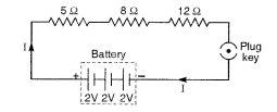
Question 2
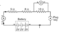
Redraw the circuit of Questions 1, putting in an ammeter to measure the current through the resistors and a voltmeter to measure the potential difference across the 12 Ω resistor. What would be the readings in the ammeter and the voltmeter ?
Solution:
The required circuit diagram is shown on the right.
Total voltage, V = 3 x 2 = 6V
Total resistance, R = 5Ω + 8Ω + 12Ω = 25Ω
Page Number: 216
Question 1
Judge the equivalent resistance when the following are connected in parallel :
(i) 1 Ω and 106 Ω,
(if) 1 Ω and 103 Ω and 106 Ω.
Answer:
When the resistances are connected in parallel, the equivalent resistance is smaller than the smallest individual resistance.
(i) Equivalent resistance < 1 Ω.
(ii) Equivalent resistance < 1 Ω.
Question 2
An electric lamp of 100 Ω, a toaster of resistance 50 Ω, and a water filter of resistance 500 Ω are connected in parallel to a 220 V source. What is the resistance of an electric iron connected to the same source that takes as much current as all three appliances, and what is the current through it ?
Solution:
Resistance of electric lamp, R1 = 100 Ω
Resistance of toaster, R2 = 50 Ω
Resistance of water filter, R3 = 500 Ω
Equivalent resistance Rp of the three appliances connected in parallel, is
Resistance of electric iron = Equivalent resistance of the three appliances connected in parallel = 31.25 Ω
Applied voltage, V = 220 V
Current, I =
Question 3
What are the advantages of connecting electrical devices in parallel with the battery instead of connecting them in series ?
Answer:
Advantages of connecting electrical devices in parallel with the battery are :
- In parallel circuits, if an electrical appliance stops working due to some defect, then all other appliances keep working normally.
- In parallel circuits, each electrical appliance has its own switch due to which it can be turned on turned off independently, without affecting other appliances.
- In parallel circuits, each electrical appliance gets the same voltage (220 V) as that of the power supply line.
- In the parallel connection of electrical appliances, the overall resistance of the household circuit is reduced due to which the current from the power supply is high.
Question 4
How can three resistors of resistances 2Ω, 3 Ω, and 6Ω be connected to give a total resistance of (i) 4 Ω, (ii) 1 Ω ?
Solution:
(i) We can get a total resistance of 4Ω by connecting the 2Ω resistance in series with the parallel combination of 3Ω and 6Ω.![]()
(ii) We can obtain a total resistance of 1Ω by connecting resistors of 2 Ω, 3 Ω and 6 Ω in parallel.![]()
Question 5
What is (i) the highest, (ii) the lowest total resistance that can be secured by combinations of four coils of resistance 4 Ω, 8 Ω, 12 Ω, 24 Ω?
Solution:
(i) Highest resistance can be obtained by connecting the four coils in series.
Then, R = 4Ω + 8Ω + 12Ω + 24Ω = 48Ω
(ii) Lowest resistance can be obtained by connecting the four coils in parallel.![]()
Page Number: 218
Question 1
Why does the cord of an electric heater not glow while the heating element does ?
Solution:
Heat generated in a circuit is given by I2R t. The heating element of an electric heater made of nichrome glows because it becomes red-hot due to the large amount of heat produced on passing current because of its high resistance, but the cord of the electric heater made of copper does not glow because negligible heat is produced in it by passing current because of its extremely low resistance.
Question 2
Compute the heat generated while transferring 96000 coulomb of charge in one hour through a potential difference of 50 V.
Solution:
Here, Q = 96,000 C, t =1 hour = 1 x 60 x 60 sec = 3,600 s, V = 50 V
Heat generated, H = VQ = 50Vx 96,000 C = 48,00,000 J = 4.8 x 10⁶ J
Question 3
An electric iron of resistance 20Ω takes a current of 5 A. Calculate the heat developed in 30 s.
Solution:
Here, R = 20 Ω, i = 5 A, t = 3s
Heat developed, H = I2 R t = 25 x 20 x 30 = 15,000 J = 1.5 x 10⁴ J
Page Number: 220
Question 1
What determines the rate at which energy is delivered by a current ?
Answer:
Resistance of the circuit determines the rate at which energy is delivered by a current.
Question 2
An electric motor takes 5 A from a 220 V line. Determine the power of the motor and the energy consumed in 2 h.
Answer:
Here, I = 5 A, V = 220 V, t = 2h = 7,200 s
Power, P = V I = 220 x 5 = 1100 W
Energy consumed = P x t = 100 W x 7200 s = 7,20,000 J = 7.2 x 10⁵ J
NCERT Solutions for Class 10 Science Chapter 12 Textbook Chapter End Questions
Question 1
A piece of wire of resistance R is cut into five equal parts. These parts are then connected in parallel. If the equivalent resistance of this combination is R’, then the ratio R/R’ is :
(a)
(b)
(c) 5
(d) 25
Answer:
(d) 25
Question 2
Which of the following terms does not represent electrical power in a circuit?
(a) I2R
(b) IR2
(c) VI
(d)
Answer:
(fa) IR2
Question 3
An electric bulb is rated 220 V and 100 W. When it is operated on 110 V, the power consumed will be :
(a) 100 W
(b) 75 W
(c) 50 W
(d) 25 W
Answer:
(d) 25 W
Question 4
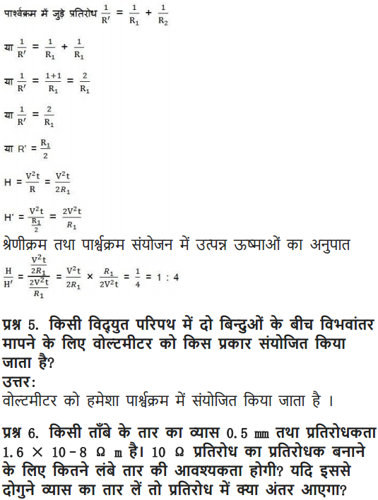
Two conducting wires of the same material and of equal lengths and equal diameters are first connected in series and then parallel in a circuit across the same potential difference. The ratio of heat produced in series and parallel combinations would be :
(a) 1 : 2
(b) 2 : 1
(c) 1 : 4
(d) 4 : 1
Answer:
(c) 1 : 4
Question 5
How is a voltmeter connected in the circuit to measure the potential difference between two points ?
Answer:
A voltmeter is connected in parallel to measure the potential difference between two points.
Question 6
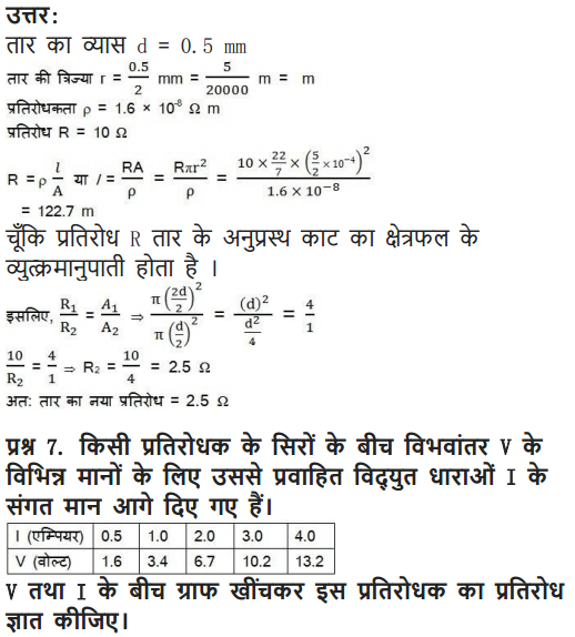
A copper wire has diameter 0.5 mm and resistivity of 1.6 x 10⁻⁸ Ω m. What will be the length of this wire to make its resistance 10 Ω ? How much does the resistance change if the diameter is doubled ?
Answer:

If a wire of diameter doubled to it is taken, then area of cross-section becomes four times.
New resistance =
Decrease in resistance = (10 – 2.5) Ω = 7.5 Ω
Question 7
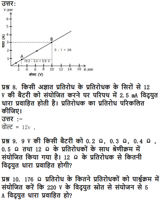
The values of current I flowing in a given resistor for the corresponding values of potential difference V across the resistor are given below :
Plot a graph between V and I and calculate the resistance of the resistor.
Solution:
The graph between V and I for the above data is given below.
The slope of the graph will give the value of resistance.
Let us consider two points P and Q on the graph.
and from P along Y-axis, which meet at point R.
Now, QR = 10.2V – 34V = 6.8V
And PR = 3 – 1 = 2 ampere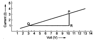
![]()
Thus, resistance, R = 3.4 Ω
Question 8
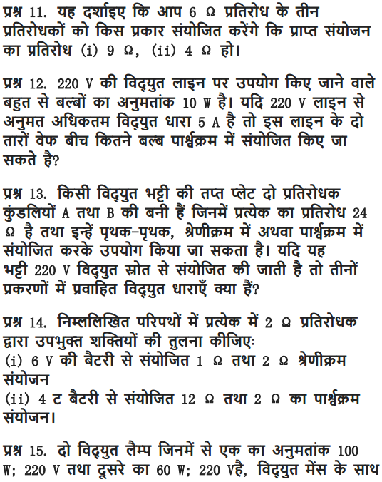
When a 12 V battery is connected across an unknown resistor, there is a current of 2.5 mA in the circuit. Find the value of the resistance of the resistor.
Solution:
Here, V = 12 V and I = 2.5 mA = 2.5 x 10⁻³ A
∴ Resistance, R =
Question 9
A battery of 9V is connected in series with resistors of 0.2 O, 0.3 O, 0.4 Q, 0.5 Q and 12 £1, respectively. How much current would flow through the 12 Q resistor?
Solution:
Total resistance, R = 0.2 Ω + 0.3 Ω + 0.4 Ω + 0.5 Ω + 12 Ω – 13.4 Ω
Potential difference, V = 9 V
Current through the series circuit, I =
∵ There is no division of current in series. Therefore current through 12 Ω resistor = 0.67 A.
Question 10
How many 176 Ω resistors (in parallel) are required to carry 5 A on a 220 V line? [CBSE (Delhi) 2013]
Solution:
Suppose n resistors of 176 Ω are connected in parallel.
Thus 4 resistors are needed to be connect.
Question 11
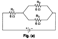
Show how you would connect three resistors, each of resistance 6 Ω, so that the combination has a resistance of (i) 9 Ω, (ii) 4Ω
Solution:
Here, R1 = R2 = R3 = 6 Ω.
(i) When we connect R1 in series with the parallel combination of R2 and R3 as shown in Fig. (a).
The equivalent resistance is
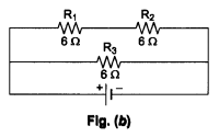
(ii) When we connect a series combination of R1 and R2 in parallel with R3, as shown in Fig. (b), the equivalent resistance is![]()
Question 12
Several electric bulbs designed to be used on a 220 V electric supply line, are rated 10 W. How many lamps can be connected in parallel with each other across the two wires of 220 V line if the maximum allowable current is 5 A ?
Solution:
Here, current, I = 5 A, voltage, V = 220 V
∴ Maxium power, P = I x V = 5 x 220 = 1100W
Required no. of lamps
∴ 110 lamps can be connected in parallel.
Question 13
A hot plate of an electric oven connected to a 220 V line has two resistance coils A and B, each of 24 Ω resistance, which may be used separately, in series, or in parallel. What are the currents in the three cases ?
Solution:
(i) When the two coils A and B are used separately. R = 24 Ω, V = 220 V![]()
(ii) When the two coils are connected in series,
(iii) When the two coils are connected in parallel.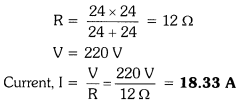
Question 14
Compare the power used in the 2 Ω resistor in each of the following circuits
(i) a 6 V battery in series with 1 Ω and 2 Ω resistors, and
(ii) a 4 V battery in parallel with 12 Ω and 2 Ω resistors.
Solution:
(i) The circuit diagram is shown in figure.
Total resistance, R = 1Ω + 2Ω = 3Ω
Potential difference, V = 6 V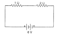
Power used in 2Ω resistor = I2R = (2)2 x 2 = 8 W
(ii) The circuit diagram for this case is shown :
Power used in 2 resistor = 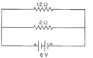
[ ∵ Current is different for different resistors in parallel combination.]
Question 15
Two lamps, one rated 100 W at 220 V, and the other 60 W at 220 V, are connected in parallel to electric mains supply. What current is drawn from the line if the supply voltage is 220 V ? [CBSE 2018]
Solution:
Power of first lamp (P1) = 100 W
Potential difference (V) = 220 V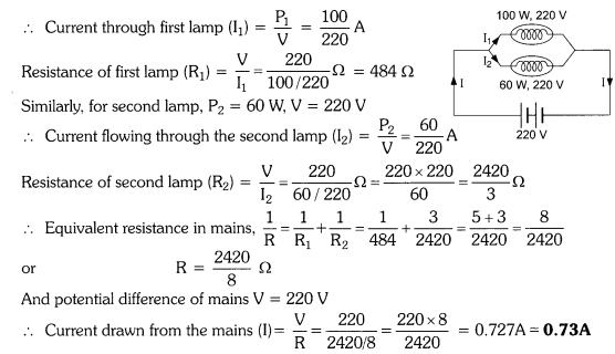
Question 16
Which uses more energy, a 250 W TV set in 1 hr, or a 1200 W toaster in 10 minutes ?
Solution:
Energy used by 250 W TV set in 1 hour = 250 W x 1 h = 250 Wh
Energy used by 1200 W toaster in 10 minutes = 1200 W x 10 min
= 1200 x
Thus, the TV set uses more energy than the toaster.
Question 17
An electric heater of resistance 8 Ω draws 15 A from the service mains 2 hours. Calculate the rate at which heat is developed in the heater.
Solution:
Here, R = 8 Ω, 1 = 15 A, t = 2 h
The rate at which heat is developed in the heater is equal to the power.
Therefore, P = I2 R = (15)2 x 8 = 1800 Js-1
Question 18
Explain the following:
(i) Why is tungsten used almost exclusively for filament of electric lamps ?
(ii) Why are the conductors of electric heating devices, such as bread-toasters and electric irons, made of an alloy rather than a pure metal ?
(in) Why is the series arrangement not used for domestic circuits ?
(iv) How does the resistance of a wire vary with its area of cross-section ?
(v) Why are copper and aluminium wires usually employed for electricity transmission?
Answer:
(i) The tungsten is used almost exclusively for filament of electric lamps because it has a very high melting point (3300°C). On passing electricity through tungsten filament, its temperature reaches to 2700°C and it gives heat and light energy without being melted.
(ii) The conductors of electric heating devices such as bread-toasters and electric irons, are made of an alloy rather than a pure metal because the resistivity of an alloy is much higher than that of pure metal and an alloy does not undergo oxidation (or burn) easily even at high temperature.
(iii) The series arrangement is not used for domestic circuits because in series circuit, if one electrical appliance stops working due to some defect, than all other appliances also stop working because the whole circuit is broken.
(iv) The resistance of a wire is inversely proportional to its area of cross-section, i.e., Resistance R ∝ (1/πr2). If the area of cross section of a conductor of fixed length is increased, then resistance decreases because there are more free electrons for movement in conductor.
(v) Copper and aluminium wires usually employed for electricity transmission because they have very low resistances. So, they do not become too hot on passing electric current.
NCERT Solutions for Class 10 Science Chapter 12 Electricity
Electric current, potential difference and electric current, Ohms law, Resistance, Resistivity factors on which the resistance of a conductor depends; Series combination of resistors, parallel combination of resistors; and its application on daily life; Heating effect of Electric current, electric Power, Interrelation between P, V, and R.
| Board | CBSE |
| Textbook | NCERT |
| Class | Class 10 |
| Subject | Science |
| Chapter | Chapter 12 |
| Chapter Name | Electricity |
| Number of Questions Solved | 41 |
| Category | NCERT Solutions |
Page 200
What does an electric circuit mean?
Electric circuit is a continuous and closed path made of conducting wires, through which the electric current flows. It comprises a cell, ammeter, voltmeter, plug key, etc.
Define the unit of current.
SI unit of electric current is ampere (A).
Ampere is the flow of electric charges through an area at the rate of one coulomb per second, i.e. if 1 coulomb of electric charge flows through a cross-section of wire for 1 second, then it would be equal to 1 ampere.
Page 202
Question 1:
Name a device that helps to maintain a potential difference across a conductor.
Answer:
Cell or battery eliminator.
Question 2:
What is meant by saying that the potential difference between two points is 1 V?
Answer:
As we know that V = W / q
Thus, the potential difference between two points is one volt when one joule of work is done to carry a charge of one coulomb between the two points in the electric field.
Question 3:
How much energy is given to one coulomb of charge passing through a 6 V battery
Answer: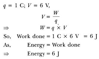
Page 209
Question 1:
On what factors does the resistance of a conductor depend
Answer:
Resistance of a conductor depends upon:
(i) Resistivity of the material.
(ii) Length of the conductor.
(iii) Cross-sectional area of the conductor.
Question 2:
Will current flow more easily through a thick wire or thin wire of the same material when connected to the same source? Why
Answer:
The current flows more easily through a thick wire than through a thin wire because the resistance of thick wire is less than that of a thin wire as R ∝ 1/A.
Download NCERT Solutions for Class 10 Science Chapter 12 Electricity PDF
Question 3:
Let the resistance of an electrical component remains constant while the potential difference across the two ends of the component decreases to half of its former value. What change will occur in the current through it?
Answer: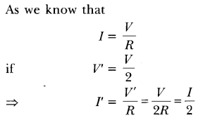
Hence, the current through an electrical component also becomes half of its previous value.
Question 4:
Why are the coils of electric toasters and electric irons made of an alloy rather than a pure metal
Answer:
The coils of electric toaster and electric iron are made of an alloy rather than a pure metal because of the following reasons;
(i) The resistivity of an alloy is higher than that of a pure metal.
(ii) It has high melting point and does not oxidise.
Question 5:
Use the data in Table 12.2 of NCERT book to answer the following:
(a) Which among iron and mercury is a better conductor?
(b) Which material is the best conductor? ‘
Answer:
(a) Iron because its resistivity is less than mercury.
(b) Silver is the best conductor as it has least resistivity.
Page 213
Question 1:
Draw a schematic diagram of a circuit consisting of a battery of three cells of 2 V each, a 5 Ω resistor, a 8 Ω resistor and a 12 Ω resistor and a plug key, all connected in series.
Answer: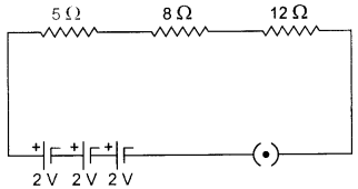
Question 2:
Redraw the circuit of the above question, putting in an ammeter to measure the current through the resistors and a voltmeter to measure the voltage across the 12 resistor. What would be the reading in the ammeter and the voltmeter?
Answer: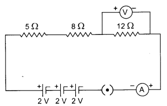
Total resistance of the circuit = R
Since all the three resistors are connected in series, so, the equivalent resistance R is equal to the sum of all resistance.
R = 5 Ω + 8 Ω + 12 Ω = 25 Ω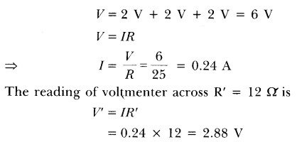
Page 216
Question 1:
Judge the equivalent resistance when the following are connected in parallel.
(a) 1 Ω and 106 Ω
(b) 1 Ω , 103 Ω and 106 Ω
Answer:
Equivalent resistance in parallel combination of resistors is always less than the least resistance of any resistor in the circuit.
Hence, in both the given cases, the equivalent resistance is less than 1 Ω.
Question 2:
An electric lamp of 100 Ω, a toaster of resistance 50 Ω and a water filter of resistance 500 Ω are connected in parallel to a 220 V source. What is the resistance of an electric iron connected to the same source that takes as much current as all three appliances and what is the current flows through it?
Answer: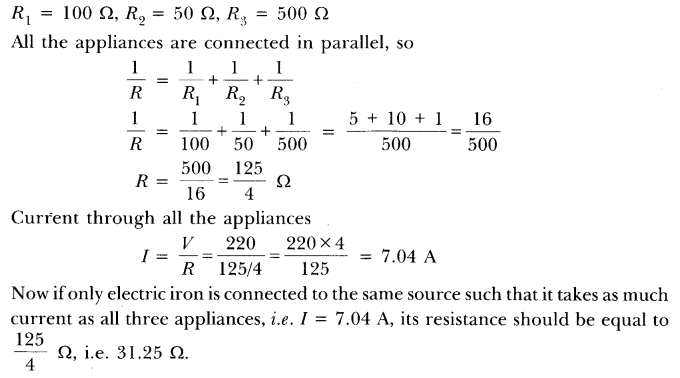
Question 3:
What are the advantages of connecting electrical devices in parallel with the battery instead of connecting them in series ?
Answer:
Advantages of connecting electrical devices in parallel:
- When the appliances are connected in parallel with the battery, each appliance gets the same potential difference as that-of battery which is not possible in series connection.
- Each appliance has different resistances and requires different currents to operate properly. This is possible only in parallel connection, as in series connection, same current flows through all devices, irrespective of their resistances.
- If one appliance fails to work, other will continue to work properly.
Question 4:
How can three resistors of resistances 2 Ω, 3 Ω and 6 Ω be connected to give a total resistance of (a) 4 Ω (b) 1 Ω?
Answer:
(a) In order to get 4 Ω, resistance 2 Ω should be connected in series with the parallel combination of 3 Ω and 6 Ω.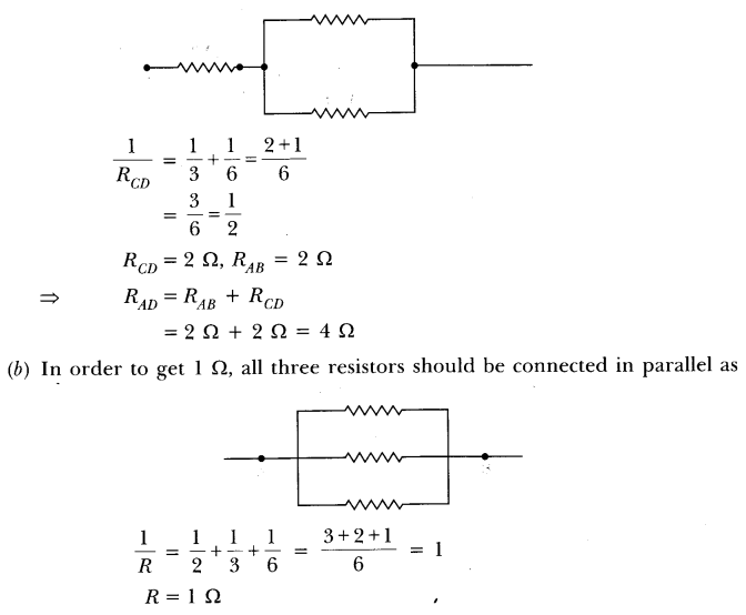
Question 5:
What is (a) the highest (b) the lowest total resistance that can be secured by combination of four coils of resistances 4 Ω, 8 Ω, 12 Ω, 24 Ω?
Answer:
(a) The highest resistance is secured by combining all four coils of resistance in series.
Rs = 4 Ω+ 8 Ω + 12 Ω + 24 Ω = 48 Ω
(b) The lowest resistance is secured by combining all four coils of resistance in parallel.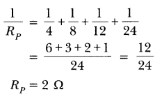
Page 218
Question 1:
Why does the cord of an electric heater not glow while the heating element does?
Answer:
The cord of an electric heater is made up of metallic wire such as copper or aluminum which has low resistance while the heating element is made up of an alloy which has more resistance than its constituent metals. Also heat produced ‘H’ is
H = I2Rt
Thus, for the same current H oc R, so for more resistance, more heat is produced by heating element and it glows.
Question 2:
Compute the heat generated while transferring 96000 C of charge in one hour through a potential difference of 50 V.
Answer:
Question 3:
An electric iron of resistance 20 Q takes a current of 5 A. Calculate the heat developed in 30 s.
Answer:
Given R = 20 Ω, I = 5 A, t = 30 s
H = I2Rt = (5)2 x 20 x 30 = 15000 J = 1.5 x 10⁴ J
Page 220
Question 1:
What determines the rate at which energy is delivered by a current?
Answer:
Electric power determines the rate at which energy is delivered by a current.
Question 2:
An electric motor takes 5 A from a 220 V line. Determine the power of the motor and the energy consumed in 2 h.
Answer:
Given I = 5 A, V = 220 V, t = 2 h Power,
p = VI = 220 x 5 = 1100 W
Energy consumed = Vlt = Pt
= 1100 x 2 = 2200 Wh
Textbook Questions
Question 1:
A piece of wire of resistance R is cut into five equal parts. These parts are then connected in parallel. If the equivalent resistance of this combination is R’, then the ratio R/R’ is
Answer: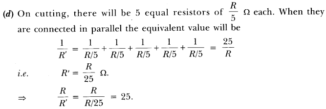
Question 2:
Which of the following terms does not represent electrical power in a circuit?
(a) I2R
(b) IR2
(c) VI
(d) V2/R
Answer:
(b) P = V2/R = I2R = VI Option (b) does not represent electrical power.
Question 3:
An electric bulb is rated 220 V and 100 W. When it is operated on 110 V, the power consumed will be
(a) 100 W
(b) 75 W
(c) 50 W
(d) 25 W
Answer:
Question 4:
Two conducting wires of same material and of equal lengths and diameters are first connected in series and then parallel in a circuit across the same potential difference. The ratio of heat produced in series and parallel combinations would be
(a) 1:2
(b) 2:1
(c) 1:4
(d) 4:1
Answer:
Question 5:
How is a voltmeter connected in the circuit to measure the potential difference between two points?
Answer:
A voltmeter is connected in parallel across any two points in a circuit to measure the potential difference between them with its +ve terminal to the point at higher potential and -ve terminal to the point at lower potential of the source.
Question 6:
A copper wire has a diameter 0.5 mm and resistivity of 1.6 X 10⁻⁸ Ωm. What will be the length of this wire to make its resistance 10 Ω? How much does the resistance change if the diameter is doubled?
Answer: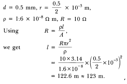
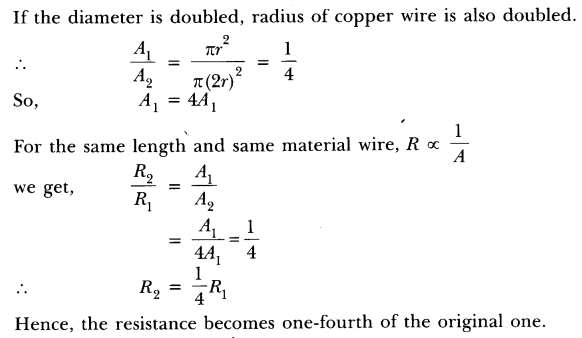
Question 7:
The values of the current I flowing in a given resistor for the corresponding values of potential difference V across the resistor are given below:
Plot a graph between V and I and calculate the resistance of that resistor.
Answer: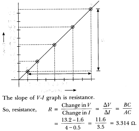
Question 8:
When a 12 V battery is connected across an unknown resistor, there is a current of 2.5 mA in the circuit. Find the value of the resistance of the resistor.
Answer:
Question 9:
A battery of 9 V is connected in series with resistors of 0.2 Ω, 0.3 Ω, 0.4 Ω, 0.5 Ω and 12 Ω, respectively. How much current would flow through the 12 Ω resistor?
Answer:
Since all the resistors are in series, the same current, 0.67 A flows through the 12 Ω resistor.
Question 10:
How many 176 Ω resistors (in parallel) are required to carry 5 A on a 220 V line?
Answer: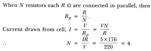
Question 11:
Show how you would connect three resistors, each of resistance 6 Ω , so that the combination has a resistance of (i) 9 Ω , (it) 4 Ω .
Answer:
(i) When two 6 Ω resistances are in parallel and the third is in combination to this, the equivalent resistance will be 9 Ω.
(ii) When two 6 Ω resistances are in series and the third is in parallel to them, then it will be 4 Ω.
Question 12:
Several electric bulbs designed to be used on a 220 V electric supply line, are rated 10 W. How many lamps can be connected in parallel with each other across the two wires of 220 V line if the maximum allowable current is 5 A?
Answer:
Since, N bulbs of power P each connected in parallel will make the total power of NP,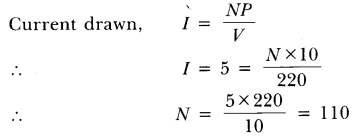
Question 13:
A hot plate of an electric oven connected to 220 V line has two resistance coils A and B, each of 24 Q resistance, which may be used separately, in series, or in parallel. What are the currents in the three cases?
Answer: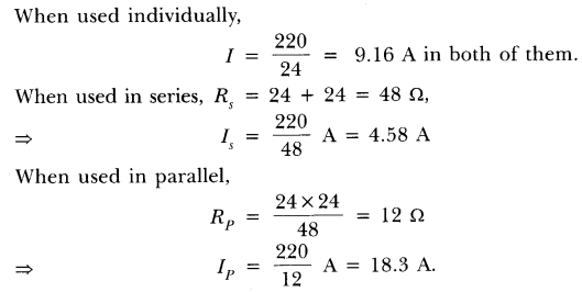
Question 14:
Compare the power used in the 2 Ω resistor in each of the following circuits.
(i) a 6 V battery in series with 1 Ω and 2 Ω resistors, and
(ii) a 4 V battery in parallel with 12 Ω and 2 Ω resistors.
Answer: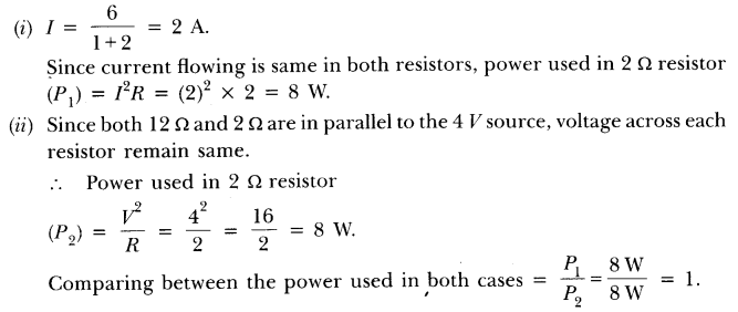
Question 15:
Two lamps, one rated 100 W at 220 V, and the other 60 W at 220 V, are connected in parallel to electric mains supply. What current is drawn from the line if the supply voltage is 220 V?
Answer:
Question 16:
Which uses more energy, a 250 W TV set in 1 hr, or a 1200 W toaster in 10 minutes?
Answer:
Energy consumed by 250 W TV set in 1 h = 250 x 1 = 250 Wh.
Energy consumed by 1200 W toaster in 10 min = 1200 X 1/6 = 200 Wh.
∴ Energy consumed by TV set is more than the energy consumed by toaster in the given timings.
Question 17:
An electric heater of resistance 8 f2 draws 15 A from the service mains 2 hours. Calculate the rate at which heat is developed in the heater.
Answer:
Question 18:
Explain the following.
(a) Why is the tungsten used almost exclusively for filament of electric lamps?
(b) Why are the conductors of electric heating devices, such as bread-toasters and electric irons, made of an alloy rather than a pure metal?
(c) Why is the series arrangement not used for domestic circuits?
(d) How does the resistance of a wire vary with its area of cross-section?
(e) Why are copper and aluminum wires usually employed for electricity transmission?
Answer:
(a) It has high melting point and emits light at a high temperature.
(b) It has more resistivity and less temperature coefficient of resistance.
(c) (i) All appliances do not get same potential in series arrangement.
(ii) All appliances cannot be individually operated.
(d) R ∝ =1 / Area of cross – section.
(e) They are very good conductors of electricity.
Short Answer Type Questions
Question 1:
Three 2 Ω resistors, A, B and C are connected as shown in figure. Each of them dissipates energy and can withstand a maximum power of 18 W without melting. Find the maximum current that can flow through the three resistors.
Answer: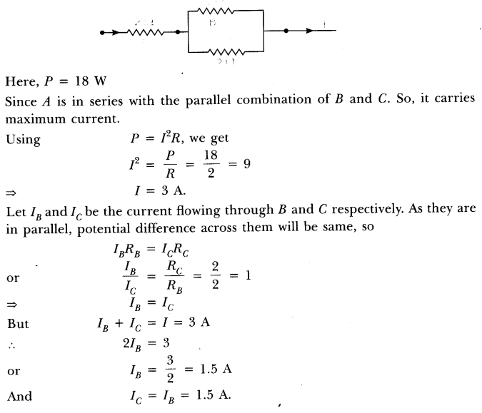
Question 2:
Should the resistance of an ammeter be low or high? Give reason.
Answer:
The resistance of an ammeter should be low so that it will not disturb the magnitude of current flowing through the circuit when connected in series in a circuit.
Question 3:
How does use of a fuse wire protect electrical appliances?
Answer:
The fuse wire is always connected in series with the live wire or electrical devices. If the flow of current exceeds the specified preset value due to some reason, the heat produced melts it and disconnects the circuit or the device from the mains. In this way, fuse wire protects the electrical appliances.
Question 4:
What is electrical resistivity? In a series electrical circuit comprising a resistor made up of a metallic wire, the ammeter reads 5 A. The reading of the ammeter decreases to half when the length of the wire is doubled. Why?
Answer:
The resistance offered by a metallic wire of unit length and unit cross-sectional area is called electrical resistivity.
Hence, when the length of wire is doubled, the resistance becomes double and current decreases to half.
Question 5:
A current of 1 ampere flows in a series circuit containing an electric lamp and a conductor of 5 Ω when connected to a 10 V battery. Calculate the resistance of the electric lamp.
Now if a resistance of 10 Ω is connected in parallel with this series combination, what change (if any) in current flowing through 5 Ω conductor and potential difference across the lamp will take place? Give reason.
Answer: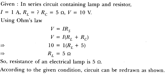
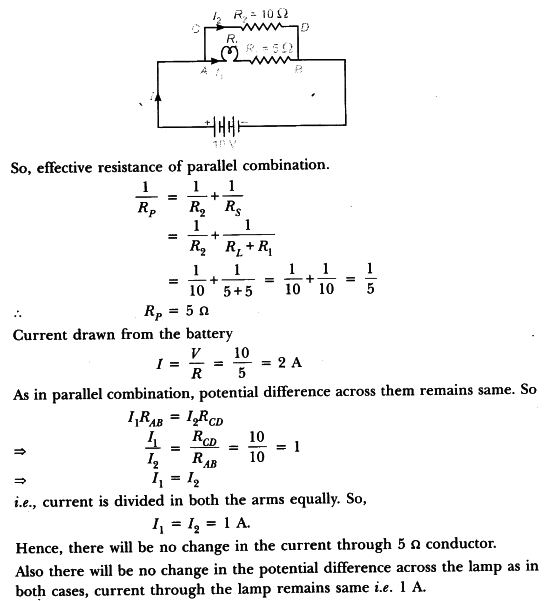
Question 6:
Why is parallel arrangement used in domestic wiring?
Answer:
Parallel arrangement is used in domestic wiring because
(i) Each appliance gets the same voltage as that of the mains supply.
(ii) If one component is switched off, others can work properly.
(iii) Fault in any branch of the circuit can be easily identified.
Question 7:
B1, B2 and B3 are three identical bulbs connected as shown in figure. When all the three bulbs glow, a current of 3A is recorded by the ammeter A.
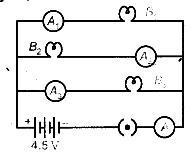
(i) What happens to the glow of the other two bulbs when the bulb B j gets fused?
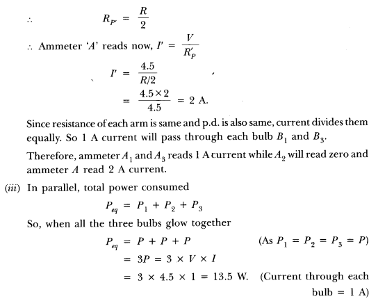
(ii) What happens to the reading of A1 ,A2 , A3 and A when the bulb B2 gets fused?
(iii) How much power is dissipated in the circuit when all the three bulbs glow together?
Answer:
(i) Since B1 ,B2 and B3 are in parallel, the potential difference across each of them will remain same. So when the bulb B1 gets fused, B2 and B3 have the same potential and continues with the same energy dissipated per second, i.e. they will glow continuously as they were glowing before.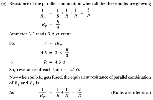
Long Answer Type Questions
Question 1:
Three incandescent bulbs of 100 W each are connected in series in an electric circuit. In another circuit, another set of three bulbs of the same wattage are connected in parallel to the same source.
(а) Will the bulb in the two circuits glow with the same brightness? Justify your answer.
(b) Now let one bulb in both the circuits get fused. Will the rest of the bulbs continue to glow in each circuit? Give reason.
Answer:
(a) The bulbs in the two circuits will not glow equally bright as the current through them is not the same.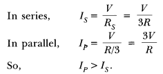
(b) As one bulb fuses, the other bulbs in the series circuit will not glow because the circuit becomes an open circuit. While the rest of bulbs in parallel circuit will continue to glow without getting disturbed because in parallel combination, current gets additional paths to flow.
Question 2:
Find out the following in the electric circuit given in figure: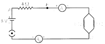
Answer: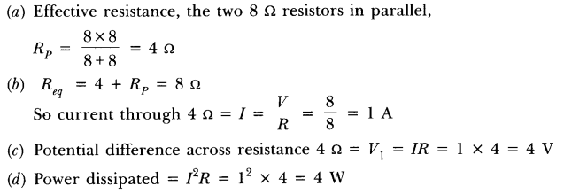
(e) No difference, since the ammeters are connected in series and same current will pass through them, so reading of both ammeters will be same.
Multiple Choice Questions (MCQs) [1 Mark each]
Question 1.
To determine the equivalent resistance of two resistors when connected in series, a student arranged the circuit components as shown in the diagram. But he did not succeed to achieve the objective. [CCE 2010]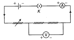
Which of the following mistakes has been committed by him in setting up the circuit?
(a) Position of ammeter is incorrect
(b) Position of voltmeter is incorrect
(c) Terminals of ammeter are wrongly connected
(d) Terminals of voltmeter are wrongly connected
Answer:
(c) Because positive terminal of ammeter must be connected with positive terminal of cell and negative terminal of an ammeter must be connected to negative terminal of a cell.
Question 2.
For the given circuit, name the components which are connected in parallel. [CCE 2011]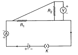
(a) R1 and R2
(b) R1, R2 and V
(c) R2 and V
(d) R1 and V
Answer:
(b) The components R1, R2 and V are connected in parallel combination. Because terminals of the resistance and voltmeter are connected together.
Question 3.
A student arranges the following circuit to get equivalent resistance of a series combination of two resistors R1 and R2.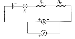
Which one of the following statements will be true for this circuit [CCE 2007]
(a) It gives incorrect reading for current I as well as potential difference V
(b) It gives correct reading for current I but incorrect reading for potential difference V
(c) It gives correct reading for potential difference V but incorrect reading for current I
(d) It gives correct reading for both I and V
Answer:
(b) The voltmeter should be connected across the components of and R2 to give correct reading for potential difference.
Question 4.
An ammeter has 20 divisions between 0 mark and 2A mark on its scale. The least count of ammeter is
(a) 0.01A
(b) 0.2A
(c) 0.1A
(d) 1A
Answer:
(c) Number of divisions = 20
Maximum reading of ammeter = 2 A
Least count of ammeter = 2/20 = 1/10 = 0.1 A
Question 5.
A student finds that there are 20 divisions between zero mark and 1V mark of a voltmeter. The least count of voltmeter is
(a) 0.1 V
(b) 0.01 V
(c) 0.05 V
(d) 1.0 V
Answer:
(c) Number of divisions = 20
Maximum reading of the voltmeter = 1 V
Least count of voltmeter = 1/20 = 0.05 V
Question 6.
The current flowing through a resistor connected in an electric circuit and the potential difference applied across its ends are shown in figure alongside.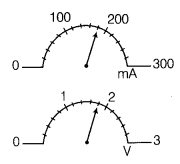
The value of the resistance of the resistor is [CCE2013]
(a) 1 Ω
(b) 5 Ω
(c) 8 Ω
(d) 10 Ω
Answer:
(d) Reading from ammeter (7) = 180 mA= 0.18 A,
reading from voltmeter (V) = 1.8 V
Resistance of the resistor R = V/I = 1.8/0.18 = 180/18 = 10Ω
Question 7.
Which of the following is the correct method to connect the ammeter and voltmeter with resistance in the circuit to verify Ohm’s law? [CCE 2012]
(a) Ammeter and voltmeter in series
(b) Ammeter in series and voltmeter in parallel
(c) Ammeter in parallel and voltmeter in series
(d) Ammeter and voltmeter in parallel
Answer:
(b) In a circuit, ammeter should be connected in series, while voltmeter in parallel.
Question 8.
In an experiment on studying the dependence of the current I flowing through a given resistor on the potential difference V applied across it, a student has to change the value of the current. For doing this, he should change the
(a) number of cells used
(b) resistor itself
(c) ammeter used in the circuit
(d) Voltmeter used in the circuit
Answer:
(a) If we change the number of cells in electric circuit, the potential difference will change and as a result current flowing in the circuit changes.
Question 9.
A milliammeter had graduations marked 0, 100, 200, 300, 400 and 500. The space between 0 mark and 100 mark is divided into 20 divisions. If the pointer of the milliammeter is indicating the seventh graduation after 300 mark, the current flowing in the circuit is
(a) 335 mA
(b) 330 mA
(c) 331mA
(d) 340 mA
Answer:
(a) Number of divisions = 20
Least count of milliammeter = (100-0) / 20 = 5 mA
Milliammeter reading = 300 + 7 x 5 = 335 mA
Question 10.
If a student while studying the dependence of current on the potential difference keeps the circuit closed for a long time to measure the current and potential difference, then
(a) ammeter’s zero error will change
(b) ammeter will give more reading
(c) voltmeter will show constantly higher readings
(d) resistor will get heated up and its value will change
Answer:
(d) If the circuit is closed for a long time, then current flows in it for a long time which results that the resistor is heated.
Question 11.
To determine the eguivalent resistance of two resistors connected in series, a student prepared two electric circuits, correct reading of ammeter in the circuits is [CCE 2015]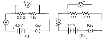
(a) In circuit I, 1.0 A and in II, 0.1 A
(b) In both circuits I and II, 1.0 A
(c) In circuit I, 0.1 A and in II, 1.0 A
(d) In both circuits I and II, 0.1 A
Answer:
(b) Equivalent resistance of two resistors 3.5Ω and 1Ω in both the circuits I and II is R = 3.5 + 1 = 4.5 Ω
As, I = V/R = 4.5/4.5 = 1A
Therefore, current in both the circuits I and II is 1.0 A.
Question 12.
When parallel resistors are of three different values, the potential difference across its terminals is [CCE 2015]
(a) greatest across smallest resistance
(b) greatest across largest resistance
(c) equal across each resistance
(d) least across the smallest resistance
Answer:
(c) Potential difference across each resistor is same in parallel combination of resistors.
NCERT Solutions for Class 10 Science Chapter 12 Electricity (Hindi Medium)
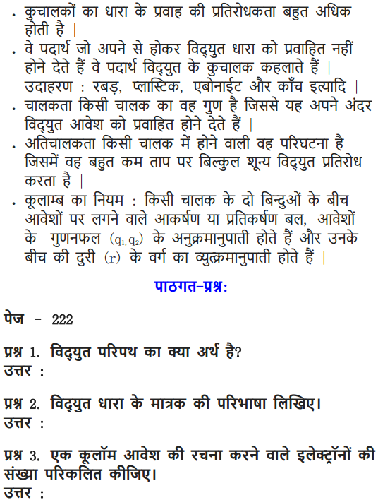
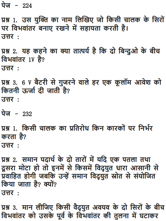
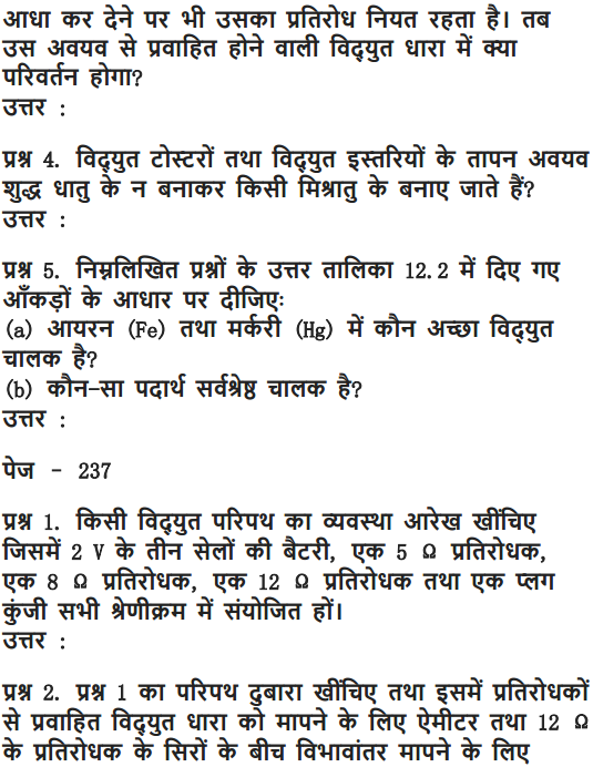
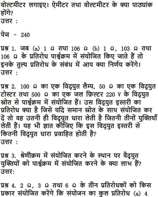
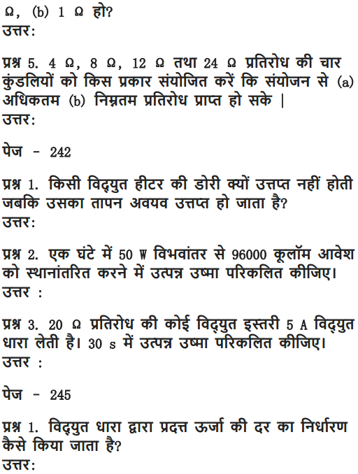
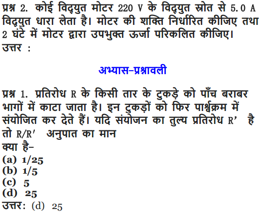
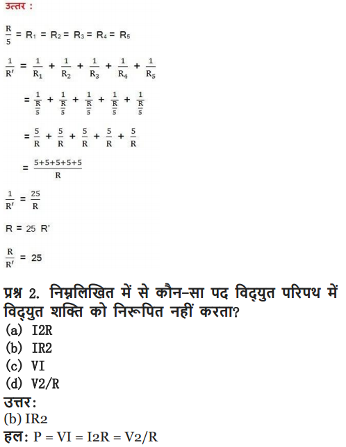
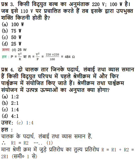
Class 10 Science Electricity Mind Map
Electricity
Study of Electric Charges at Rest and in Motion
Charge
Something associated with the matter due to which it produces and experiences electric and magnetic effects. Resides on the outer surface of the conductor.
Q = ne S.I. unit coulomb (C)
Electric Current (I)
The time rate of flow of charge (Q) through any cross-section
I =
Types of Current
Direct Current
Current whose magnitude and direction does not vary with time.
Alternating Current
Current whose magnitude and direction periodically changes with time.
Electric Potential
Work done per unit charge
V =
S.I. unit volt
Ohm’s law: If the physical conditions remain same, current I ∝ V => V = IR
R-electric resistance Substances which obey ohm’s law called ohmic and that do not obey called non-ohmic substances.
Dependence of Resistance
On length (l) and area of cross-section (A)
R ∝ l
∝
R =
ρ = resistivity
Resistivity depends on the material of the conductor only.
On Temperature
Rt = R0( 1 + αt)
α = temperature coefficient of resistance
Resistance (R): Obstruction offered to flow of electrons.
SI unit ohm
Resistance, R ∝
l = length and
m = mass of conducting wire
After stretching, if length increases by n times then resistance will increase by n2 times i.e., R2 = n2 R1. Similarly
if radius be reduced to
After stretching, if length of a conductor increases by x%, then resistance will increase by 2x% (valid only if x< 10%).
- Using n conductors of equal resistance, the number of possible combinations is 2n-1 .
- If the resistances of n conductors are totally different, then the number of possible combinations will be 2n .
- If n identical resistances are first connected in series and then in parallel, the ratio of the equivalent resistance is given by
RsRp=n21 - If a wire of resistance R is cut in n equal parts and then these parts are collected to form a bundle, then equivalent resistance of combination will be
Rn2 - If equivalent resistance of R1 and R2 in series and parallel be Rs and Rp respectively, then
R1 =12[Rs+R2s−4RsRp−−−−−−−−−−√]
and R2 ==12[Rs−R2s−4RsRp−−−−−−−−−−√]
Grouping of Resistances
Series Grouping of Resistances
Equivalent resistance, resistance, Rs = R1 + R2 + … + Rn
In this case same current flows through each resistance but potential difference in the ratio of resistance
Parallel Grouping of Resistances
In this case same potential across each resistance but current distributes in the reverse ratio of their resistances
Electric Circuit
The arrangement of various electrical components along which electric current flow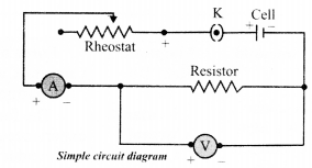
Heating Effect of Electric Current
As current flows through a conductor, the free electrons lose energy which is converted into heat.
Joule’s heating law
H ∝ I2
H ∝ R
H ∝ t
H = I2Rt = VIt
Practical Applications
- Electric heater, electric iron and water heater, etc. work on the principle of heating effect of current
- Electric bulb glows when electric current flows through the filament of the bulb
Electric Power
Rate at which electric energy is dissipated or consumed in a circuit,
P = VI ,
or P = I2R =
Watt is a smaller unit of power, its other bigger units are kilowatt (KW),
Megawatt (MW) and Horsepower (HP)
1 KW = 103W 1 MW = 106W
1 hp =746 W
The commercial unit of electrical energy is 1 Kwh.
1 Kwh = 3.6 × 10⁶J
Elements of Circuit
Cell
Direct current source of electromotive force. Combination of two or more cells is called battery.![]()
Rheostat
Wire of special type of alloy like manganin, Eureka, nichrome, etc. is wound on a hollow cylinder of china clay. It controls the current in the electric circuit.![]()
Switch
It is used to close or open the electric circuit, controls the movement of electrons in a circuit.
Voltmeter
Measures the potential difference between two points in the circuit. Its resistance is high and it is used in parallel with the resistance wire.![]()
Fuse
It is a safety device having very thin wire which is made up of either tin or alloy of tin and lead.
This wire has low melting point so it melts and breaks the circuit easily if the current in the circuit exceeds.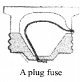
Ammeter
Measures the value of current flowing in the circuit.
The resistance of ammeter is small and it is used in series with the circuit.![]()
LED
It is a device which glows even if a weak electric current is allowed to flow through it
Important Questions of Electricity Class 10 Science Chapter 12
Question 1.
A current of 10 A flows through a conductor for two minutes.
(i) Calculate the amount of charge passed through any area of cross section of the conductor.
(ii) If the charge of an electron is 1.6 × 10⁻¹⁹ C, then calculate the total number of electrons flowing. (Board Term I, 2013)
Answer:
Given that: I = 10 A, t = 2 min = 2 × 60 s = 120 s
(i) Amount of charge Q passed through any area of cross-section is given by I =
or Q = I × t ∴ Q = (10 × 120) A s = 1200 C
(ii) Since, Q = ne
where n is the total number of electrons flowing and e is the charge on one electron
∴ 1200 = n × 1.6 × 10⁻¹⁹
or n =
Question 2.
Define electric current. (1/5, Board Term 1,2017)
Answer:
Electric current is the amount of charge flowing through a particular area in unit time.
Question 3.
Define one ampere. (1/5, Board Term 1,2015)
Answer:
One ampere is constituted by the flow of one coulomb of charge per second.
1 A = 1 C s-1
Question 4.
Name a device that you can use to maintain a potential difference between the ends of a conductor. Explain the process by which this device does so. (Board Term I, 2013)
Answer:
A cell or a battery can be used to maintain a potential difference between the ends of a conductor. The chemical reaction within a cell generates the potential difference across the terminals of the cell, even when no current is drawn from it. When it is connected to a conductor, it produces electric current and, maintain the potential difference across the ends of the conductor.
Question 5.
Draw the symbols of commonly used components in electric circuit diagrams for
(i) An electric cell
(ii) Open plug key
(iii) Wires crossing without connection
(iv) Variable resistor
(v) Battery
(vi) Electric bulb
(vii) Resistance (4/5, Board Term 1,2017)
Answer: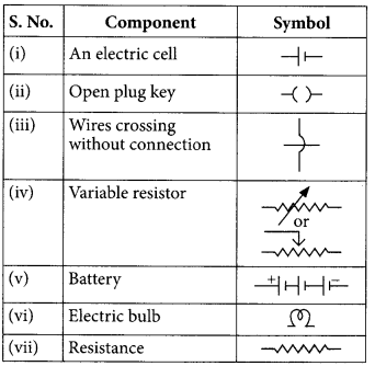
Question 6.
A student plots V-I graphs for three samples of nichrome wire with resistances R1, R2 and R3. Choose from the following the statements that holds true for this graph. (2020)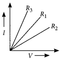
(a) R1 = R2 = R3
(b) R1 > R2 > R3
(c) R3 > R2 > R1
(d) R2 > R1 > R3
Answer:
(d) : The inverse of the slope of I-V graph gives the resistance of the material. Here the slope of -Rj is highest. Thus, R2 > R1 > R3
Question 7.
State Ohms law. (AI 2019)
Answer:
It states that the potential difference V, across the ends of a given metallic wire in an electric circuit is directly proportional to the current flowing through it, provided its temperature remains the same. Mathematically,
V ∝ I
V = RI
where R is resistance of the conductor.
Question 8.
A V-I graph for a nichrome wire is given below. What do you infer from this graph? Draw a labelled circuit diagram to obtain such a graph. (2020)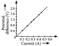
Answer:
As graph is a straight line, so it is clear from the graph that V ∝ I.
The shape of the graph obtained by plotting potential difference applied across conductor against the current flowing v. llmuigh il will be a straight line.
According to ohms law,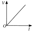
V = IR or R =
So, the slope of V’-/ graph at any point represents the resistance of the given conductor.
Question 9.
Study the V-I graph for a resistor as shown in the figure and prepare a table showing the values of I (in amperes) corresponding to four different values V (in volts). Find the value of current for V = 10 volts. How can we determine the resistance of the resistor from this graph? (Board Term I, 2016)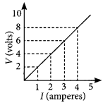
Answer:
Since, the graph is straight line so we can either extrapolate the data or simply mark the value from graph as shown in figure.
| Current, I(A) | Voltage, V(V) |
| 0 | 0 |
| 1 | 2 |
| 2 | 4 |
| 3 | 6 |
| 4 | 8 |
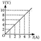
Hence, the value of current for V = 10 volts is 5 amperes (or 5 A).
From Ohm’s law, V = IR,
We can write, R =
At any point on the graph, resistance is the ratio of values of V and I. Since, the given graph is straight line (ohmic conductor) so, the slope of graph will also give the resistance of the resistor
R =
Alternately, R =
Question 10.
V-I graph for a conductor is as shown in the figure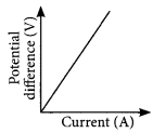
(i) What do you infer from this graph?
(ii) State the law expressed here. (Board Term I, 2014)
Answer:
(i) Refer to answer 8.
(ii) Refer to answer 7.
Question 11.
State Ohm’s law. Draw a labelled circuit diagram to verify this law in the laboratory. If you draw a graph between the potential difference and current flowing through a metallic conductor, what kind of curve will you get? Explain how would you use this graph to determine the resistance of the conductor. (Board Term I, 2016)
Answer:
Refer to answer 7 and 8.
Question 12.
State and explain Ohm’s law. Define resistance and give its SI unit. What is meant by 1 ohm resistance? Draw V-I graph for an ohmic conductor and list its two important features. (Board Term I, 2014)
Answer:
Ohm’s law: Refer to answer 7.
Resistance : It is ihe properly of a conductor lo resist the How of charges through it.
Its SI unit is ohm (Ω). If the potential difference across the two ends of a conductor is 1 V and the current through it is 1 A, then the resistance R, of the conductor is 1 ohm (1 Ω). lvolt
1 ohm =
V-I graph for an ohmic conductor can be drawn as given in figure.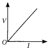
Important feature of V-I graph are:
(i) It is a straight line passing through origin.
(ii) Slope of V-I graph gives the value of resistance of conductor slope = R =
Question 13.
Assertion (A) : The metals and alloys are good conductors of electricity.
Reason (R) : Bronze is an alloy of copper and tin and it is not a good conductor of electricity.
(a) Both (A) and (R) are true and (R) is the correct explanation of the assertion (A).
(b) Both (A) and (R) are true, but (R) is not the correct explanation of the assertion (A).
(c) (A) is true, but (R) is false.
(d) (A) is false, but (R) is true. (2020)
Answer:
(c) : Metals and alloys are good conductors of electricity. Bronze is an alloy of copper and tin which are metals and thus is a good conductor of electricity.
Question 14.
A cylindrical conductor of length ‘l’ and uniform area of cross section ‘A’ has resistance ‘R’. The area of cross section of another conductor of same material and same resistance but of length ‘2l’ is (2020)
(a)
(b)
(c) 2A
(d) 3A
Answer:
(c) : The resistance of a conductor of length!, and area of cross section, A is
R = ρ
where ρ is the resistivity of the material.
Now for the conductor of length 21, area of cross-section A’ and resistivity ρ.
R’ = ρ
But given, R = R’ ⇒ ρ
Question 15.
Assertion (A) : Alloys are commonly used in electrical heating devices like electric iron and heater.
Reason (R): Resistivity of an alloy is generally higher than that of its constituent metals but the alloys have low melting points then their constituent metals.
(a) Both (A) and (R) are true and (R) is the correct explanation of the assertion (A).
(b) Both (A) and (R) are true, but (R) is not the correct explanation of the assertion (A).
(c) (A) is true, but (R) is false.
(d) (A) is false, but (R) is true. (2020)
Answer:
(a)
Question 16.
How is the resistivity of alloys compared with those of pure metals from which they may have been formed? (Board Term I, 2017)
Answer:
The resistivity of an alloy is generally higher than that of its constituent metals.
Question 17.
(i) List three factors on which the resistance of a conductor depends.
(ii) Write the SI unit of resistivity. (Board Term 1, 2015)
Answer:
(i) Resistance of a conductor depends upon the following factors:
(1) Length of the conductor : (Treater the length (I) of the conductor more will be the resistance (R).
R ∝ I
(2) Area ol cross section of the conductor: (Ireater the cross-sectional area of the conductor, less will be the resistance.
R ∝
(3) Nature of conductor.
(ii) SI unit of resistivity is Ω m.
Question 18.
Calculate the resistance of a metal wire of length 2m and area of cross section 1.55 × 10⁶ m², if the resistivity of the metal be 2.8 × 10⁻⁸ Ωm. (Board Term I, 2013)
Answer:
For the given metal wire,
length, l = 2 m
area of cross-section, A = 1.55 × 10⁻⁶ m²
resistivity of the metal, p = 2.8 × 10⁻⁸ Ω m
Since, resistance, R = ρ
So R = (
=
Question 19.
(a) List the factors on which the resistance of a conductor in the shape of a wire depends.
(b) Why are metals good conductors of electricity whereas glass is a bad conductor of electricity ? Give reason.
(c) Why are alloys commonly used in electrical heating devices ? Give reason. (2018)
Answer:
(a) Refer to answer 17 (i).
(b) Metal have very low resistivity and hence they are good conductors of electricity.
Whereas glass has very high resistivity so glass is a bad conductor of electricity.
(c) Alloys are commonly used in electrical heating devices due to the following reasons
(i) Alloys have higher resistivity than metals
(ii) Alloys do not get oxidised or burn readily.
Question 20.
Calculate the resistivity of the material of a wire of length 1 m, radius 0.01 cm and resistance 20 ohms. (Board Term I, 2017)
Answer:
We are given, the length of wire, l = 1 m, radius of wire, r = 0.01 cm = 1 × 10⁻⁴ m and resistance, R = 20Ω As we know,
R = ρ
∴ 20Ω.= ρ
∴ ρ = 6.28 × 10⁻⁷ Ω m
Question 21.
A copper wire has diameter 0.5 mm and resistivity 1.6 × 10⁻⁸ Ω m. Calculate the length of this wire to make it resistance 100 Ω. How much does the resistance change if the diameter is doubled without changing its length? (Board Term I, 2015)
Answer:
Given; resistivity of copper = 1.6 × 10⁻⁸ Ω m, diameter of wire, d = 0.5 mm and resistance of wire, R = 100 Ω
Radius of wire, r =
= 0.25 mm = 2.5 × 10⁻⁴ m
Area of cross-section of wire, A = nr²
∴ A = 3.14 × (2.5 × 10-4)²
= 1.9625 × 10⁻⁷ m²
= 1.9 × 10⁻⁷ m²
As, R = ρ
∴ 100 Ω =
l = 1200 m
If diameter is doubled (d’ = 2d), then the area of cross-section of wire will become
A’ = πr² = π(
Now R ∝
R’ =
Question 22.
The resistance of a wire of 0.01 cm radius is 10 Ω. If the resistivity of the material of the wire is 50 × 10-8 ohm meter, find the length of the wire. (Board Term I, 2014)
Answer:
Here, r = 0.01 cm = 10-4 m, ρ = 50 × 10-8 Ω m and R = 10 Ω
As, R = ρ
or l =
so l =
= 0.628 m = 62.8 cm
Question 23.
A wire has a resistance of 16 Ω. It is melted and drawn into a wire of half its original length. Calculate the resistance of the new wire. What is the percentage change in its resistance? (Board Term I, 2013)
Answer:
When wire is melted, its volume remains same, so,
V’ = V or A’l’ = Al
Here, l’ =
Therefore, A’ = 2 A
Resistance, R = ρ
Now, R’ =
So, R’ =
Percentage change in resistance,
=
Question 24.
If the radius of a current carrying conductor is halved, how does current through it change? (2/5 Board Term I, 2014)
Answer:
If the radius of conductor is halved, the area of cross-section reduced to (
Since, R ∝
From Ohm’s law, V = IR
For given V, I ∝
So, current will reduce to one-fourth of its previous value.
Question 25.
Define resistance of a conductor. State the factors on which resistance of a conductor depends. Name the device which is often used to change the resistance without changing the voltage source in an electric circuit. Calculate the resistance of 50 cm length of wire of cross sectional area 0.01 square mm and of resistivity 5 × 10⁻⁸ Ω m. (Board Term I, 2014)
Answer:
Resistance is the property of a conductor to resist the flow of charges through it.
Factors affecting resistance of a conductor:
Refer to answer 17(i)
Rheostat is the device which is often used to change the resistance without changing the voltage source in an electric circuit.
We are given, length of wire, l = 50 cm = 50 × 10-2 m cross-sectional area, A = 0.01 mm²
= 0.01 × 10⁻⁶ m²
and resistivity, ρ = 5 x 10⁻⁸ Ω m.
As, resistance, R = ρ
∴ R =
= 2.5 Ω
Question 26.
If a person has five resistors each of value
(a) 1 Ω
(b) 5 Ω
(c) 10 Ω
(d) 25 Ω (2020)
Answer:
(a) The maximum resistance can be obtained from a group of resistors by connecting them in series. Thus,
Rs =
Question 27.
The maximum resistance which can be made using four resistors each of 2 Ω is
(a) 2 Ω
(b) 4 Ω
(c) 8 Ω
(d) 16 Ω (2020)
Answer:
(c) : A group of resistors can produce maximum resistance when they all are connected in series.
∴ Rs = 2 Ω + 2 Ω + 2 Ω + 2 Ω = 8 Ω
Question 28.
The maximum resistance which can be made using four resistors each of resistance
(a) 2 Ω
(b) 1 Ω
(c) 2.5 Ω
(d) 8 Ω (2020)
Answer:
(a) The maximum resistance can be produced from a group of resistors by connecting them in series.
Thus, Rs =
Question 29.
Three resistors of 10 Ω, 15 Ω and 5 Ω are connected in parallel. Find their equivalent resistance. (Board Term I, 2014)
Answer:
Here, R1 = 10 Ω, R2 =15 Ω, R3 = 5 Ω.
In parallel combination, equivalent resistance, (Req) is given by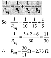
Question 30.
List the advantages of connecting electrical devices in parallel with an electrical source instead of connecting them is series. (Board Term I, 2013)
Answer:
(a) When a number of electrical devices are connected in parallel, each device gets the same potential difference as provided by the battery and it keeps on working even if other devices fail. This is not so in case the devices are connected in series because when one device fails, the circuit is broken and all devices stop working.
(b) Parallel circuit is helpful when each device has different resistance and requires different current for its operation as in this case the current divides itself through different devices. This is not so in series circuit where same current flows through all the devices, irrespective of their resistances.
Question 31.
Show how would you join three resistors, each of resistance 9 Ω so that the equivalent resistance of the combination is (i) 13.5 Ω, (ii) 6 Ω (2018)
Answer:
(i) The resistance of the series combination is higher than each of the resistances. A parallel combination of two 9 Ω resistors is equivalent to 4.5 Ω. We can obtain 13.5 Ω by coupling 4.5 Ω and 9 Ω in series. So, to obtain 13.5 Ω, the combination is as shown in figure (a).
(ii) To obtain a equivalent resistance of 6 Ω, we have to connect two 9 Ω resistors in series and then connect the third 9 Ω resistor in parallel to the series combination as shown in the figure (b).
Question 32.
Three resistors of 3 Ω each are connected to a battery of 3 V as shown. Calculate the current drawn from the battery. (Board Term I, 2017)
Answer:
As given in circuit diagram, two 3 Ω resistors are connected in series to form R1; so R1 = 3 Ω + 3 Ω = 6 Ω
And, R1 and R2 are in parallel combination, Hence, equivalent resistance of circuit (Req) given by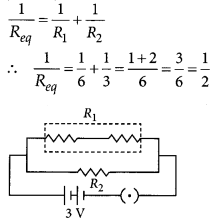
Req = 2 Ω
Using Ohm’s law, V = IR
We get,
3 V = I × 2 Ω
or I =
Current drawn from the battery is 1.5 A.
Question 33.
Two identical resistors are first connected in series and then in parallel. Find the ratio of equivalent resistance in two cases. (Board Term I, 2013)
Answer:
Let resistance of each resistor be R.
For series combination,
Rs = R1 + R2
So, Rs = R + R = 2R
For parallel combination,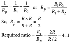
Question 34.
(a) A 6 Ω resistance wire is doubled on itself. Calculate the new resistance of the wire.
(b) Three 2 Ω resistors A, B and C are connected in such a way that the total resistance of the combination is 3 Ω. Show the arrangement of the three resistors and justify your answer. (2020)
Answer:
(a) Given resistance of wire, R = 6 Ω
Let l be the length of the wire and A be its area of
cross-section. Then
R =
Now when the length is doubled, l’ = 2l and A’ =
∴ R’ =
(b) Given the total resistance of the combination = 3 Ω
In order to get a total resistance of 3 Ω, the three resistors has to be connected as shown.
Such that,
⇒ Rp = 1 Ω
and Rs = 2 Ω + 1 Ω = 3 Ω
Question 35.
Draw a schematic diagram of a circuit consisting of a battery of 3 cells of 2 V each, a combination of three resistors of 10 Ω, 20 Ω and 30 Ω connected in parallel, a plug key and an ammeter, all connected in series. Use this circuit to find the value of the following :
(a) Current through each resistor
(b) Total current in the circuit
(c) Total effective resistance of the circuit. (2020)
Answer:
The circuit diagram is as shown below.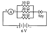
(a) Given, voltage of the battery = 2V + 2V + 2V = 6 V
Current through 10 Ω resistance,
I10 =
Current through 20 Ω resistance,
I20 =
Current through 30 Ω resistance,
I30 =
(b) Total current in the circuit, 1= I10 + I20 + I30
= 0.6 + 0.3 + 0.2 = 1.1 A
(c) Total resistance of the circuit,
Question 36.
(a) With the help of a suitable circuit diagram prove that the reciprocal of the equivalent resistance of a group of resistances joined in parallel is equal to the sum of the reciprocals of the individual resistances.
(b) In an electric circuit two resistors of 12 Ω each are joined in parallel to a 6 V battery. Find the current drawn from the battery. (Delhi 2019)
Answer:
(a) Resistors in parallel : When resistors are connected in parallel.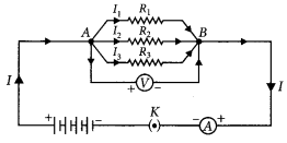
(i) The potential difference across their ends is the same.
(ii) The sum of current through them is the current drawn from the source of energy or cell.
I = I1 + I1 + I3 or
(iii) The equivalent resistance is given by,
Hence equivalent resistance in parallel combination is equal to the sum of reciprocals of the individual resistances.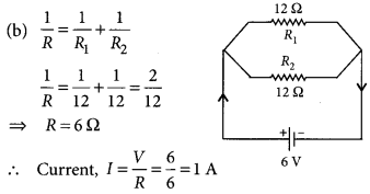
Question 37.
For the series combination of three resistors current in each resistor, establish the relation R = R1 + R2 + R3 where the symbols have their usual meanings. Calculate the equivalent resistance of the combination of three resistors of 6 Ω, 9 Ω and 18 Ω joined in parallel. (Board Term I, 2016)
Answer: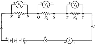
Given figure shows the series combination of three resistors R1, R2 and R3 connected across a voltage source of potential difference V.
Let current I is flowing through the circuit.
V1, V2 and V3 are the potential differences across resistors R1, R2 and R3 respectively.
Since, the total potential difference across a combination of resistors in series is equal to the sum of potential difference across the individual resistors.
∴ v = v1 + v2 + v3 …(i)
In series current through each resistor is same. Applying the Ohms law,
V1 = IR1, V2 = IR2 and V3 = IR1 ……..(ii)
If Rs is the equivalent resistance of the circuit, then
V = IRs …(iii)
From eqns. (i), (ii) and (iii),
we can write IRs = IR1 + IR2 + IR3
or Rs = R1 + R2 + R3
We can conclude that when several resistors are joined in series, the resistance of the combination Rs equals the sum of their individual resistances,
R1, R2 and R3
Given : R1 = 6 Ω, R2 = 9 Ω,
R3 = 18 Ω are connected in parallel.
Equivalent resistance, Req, is given by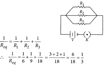
or Req = 3 Ω
Question 38.
State ohms law. Represent it graphically. In the given circuit diagram calculate
(i) the total effective resistance of the circuit.
(ii) the current through each resistor.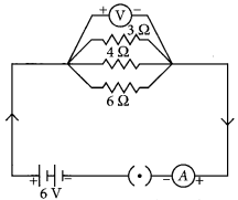
Answer:
Ohm’s law: Refer to answer 7.
Graphical representation of Ohm’s law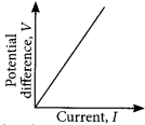
For the given circuit
R1 = 3 Ω, R2 = 4 Ω., R3 = 6 Ω and V = 6V.
(i) Total effective resistance of the circuit, Req is given by
or Req =
(ii) Since, potential difference across each resistor connected in parallel is same.
So, V1 = V2 = V3 = 6 V
Applying Ohm’s law,
V1 = I1R1 or I1 =
Similarly, I2 =
Question 39.
(a) Prove that the equivalent resistance of three resistors R1, R2 and R3 in series is R1 + R2 + R3
(b) You have four resistors of 8 Ω each. Show how would you connect these resistors to have effective resistance of 8 Ω? (4/5, Board Term I, 2015)
Answer:
(a) Refer to answer 37.
(b) If you have four 8 Ω resistors and the effective resistance is also 8 Ω then the two 8 Ω resistors are connected in series. Now you have pair of two 16 Ω resistors (8 Ω + 8 Ω). If you connect these resistors in parallel, you will have net resistance 8 Ω.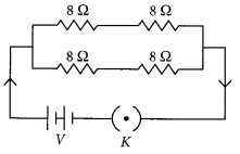
Question 40.
Draw a labelled circuit diagram showing three resistors R1, R2 and R3 connected in series with a battery (E), a rheostat (Rh), a plug key (K) and an ammeter (A) using standard circuit symbols. Use this circuit to show that the same current flows through every part of the circuit. List two precautions you would observe while performing the experiment. (Board Term I, 2014)
Answer: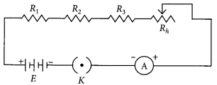
Change the positions of ammeter and note the reading of ammeter each time. You will find that all the reading obtained are same.
So, the value of the current in the ammeter is the same, independent of its position in the electric circuit. It means that in this circuit (series combination) the current is the same in every part of the circuit.
Precautions:
(i) All the connections are neat and tight.
(ii) Ammeter is connected with the proper polarity, i.e., positive terminal of the ammeter should go to positive terminal and negative terminal of ammeter to the negative terminal of the battery or cell used.
Question 41.
Two wires A and B are of equal length and have equal resistances. If the resistivity of A is more than that of B, which wire is thicker and why ? For the electric circuit given below calculate: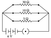
(i) current in each resistor
(ii) total current drawn from the battery, and
(iii) equivalent resistance of the circuit. (Board Term I, 2014)
Answer:
Let lA, aA and RA be the length, area of cross-section and resistance of wire A and lB, aB and RB are that of wire B.
Here, lA = lB and RA = RB
If ρA and ρB are the resistivities of wire A and B respectively then
RA = ρA
∴ ρA
or
Since ρA > ρB therefore aA > aB Hence, wire A is thicker than wire B.
For parallel combination,
V1 = V2 = V3 = 6V
(i) Using Ohm’s law
I1 = V1/R1 = 6/30 = 0.2 A
I2 = V2/R2 = 6/10 = 0.6 A
I3 = V3/R3 = 6/5 = 1.2 A
(ii) Total current drawn from battery,
I = I1 + I2 + I3 = 0.2 + 0.6 + 1.2 = 2 A
(iii) Equivalent resistance of the circuit, Req can be obtained by Ohm’s law
V= I Req
So, 6 V = 2 A × Req or, Req =
Aliter,
or Req = 3 Ω
Question 42.
(a) Derive an expression to find the equivalent resistance of three resistors connected in series. Also draw the schematic diagram of the circuit.
(b) Find the equivalent resistance of the following circuit.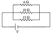
Answer:
(a) Refer to answer 37.
(b) For the given circuit,
R1 = 6 Ω, R2 = 10 Ω, R3 = 15 Ω.
As
=
Req = 3 Ω
Question 43.
Draw a circuit diagram for a circuit consisting of a battery of five cells of 2 volts each, a 5 Ω resistor, a 10 Ω resistor and a 15 Ω resistor, an ammeter and a plug key, all connected in series. Also connect a voltmeter to record the potential difference across the 15 Ω resistor and calculate
(i) the electric current passing through the above circuit and
(ii) potential difference across 5 Ω resistor when the key is closed. (Board Term 1, 2013)
Answer: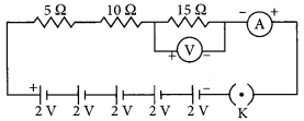
Potential of the battery, V = (2 × 5) V = 10 V
Equivalent resistance,
Req = R1 + R2 + R3
= (5 + 10 + 15)Ω = 30 Ω
(i) Current through circuit, I =
(ii) Potential across 5 Ω resistor, V1 = IR1
=
Question 44.
The resistance of a resistor is reduced to half of its initial value. In doing so, if other parameters of the circuit remain unchanged, the heating effects in the resistor will become
(a) two times
(b) half
(c) one-fourth
(d) four times (2020)
Answer:
(a) : We know, H = I²Rt =
Now when, R’ =
H’ =
Question 45.
(a) Write the mathematical expression for Joules law of heating.
(b) Compute the heat generated while transferring 96000 coulomb of charge in two hours through a potential difference of 40 V. (2020)
Answer:
(a) The Joule’s law of healing implies that heat produced in a resistor is
(i) directly proportional to the square of current lor a given resistance,
(ii) directly proportional to resistance for a given current, and
(iii) directly proportional to the time for which the current flows through the resistor.
i.e., H = I² Rt
(b) Given, charge q = 96000 C, time t = 2 h = 7200 s and potential difference V = 40 V
We know, H = I²Rt =
= 40 × 96000 = 3.84 × 10⁶ J = 3.84 MJ
Question 46.
Write Joules law of heating. (1/3, 2018)
Answer:
Refer to answer 45(a).
Question 47.
Explain the use of an electric fuse. What type of material is used for fuse wire and why? (Board Term I, 2016)
Answer:
Electric fuse protects circuits and appliances by stopping the flow of any unduly high electric current. It consists of a piece of wire made of a metal or an alloy of appropriate melting point, for example aluminium, copper, iron, lead etc. If a current larger than the specified value flows through the circuit, the temperature of the fuse wire increases. This melts the fuse wire and breaks the circuit.
Question 48.
(a) Why is tungsten used for making bulb filaments of incandescent lamps?
(b) Name any two electric devices based on heating effect of electric current. (2/5, Board Term I, 2015)
Answer:
(a) (i) Tungsten is a strong metal and has high melting point (3380°C).
(ii) It emits light at high temperatures (about 2500°C).
(b) Electric laundry iron and electric heater are based on heating effect of electric current.
Question 49.
A fuse wire melts at 5 A. If it is desired that the fuse wire of same material melt at 10 A, then whether the new fuse wire should be of smaller or larger radius than the earlier one? Give reasons for your answer. (3/5, Board Term I, 2014)
Answer:
Let the resistance of the wire be R, heat produced in the fuse at 5 A in Is is
H=(5)²R ( H – I²Rt)
50. fuse melts at (5)²R joules of heat.
Let, the resistance of new wire is R’
So, heat produced in 1 second = (10)²R’
To prevent it from melting
(5)²R = (10)²R’ or R’ =
As R ∝
∴ cross-sectional area of new fuse wire is four times the first fuse.
Now, A = πr², so new radius is twice the previous one. So, at 10 A, the new fuse wire of same material and length has larger radius than the earlier one.
Question 50.
What is heating effect of current? List two electrical appliances which work on this effect. (2/5, Board Term I, 2013)
Answer:
If only resislors are connected to the battery, the source energy continually gets dissipated entirely in the form of heal. This is known as healing effect of current, ’file amount of heat (77) produced in time t is given by Joule’s law of heating.
H = I²Rt
Where, 7 is current flowing through resistor R.
The electric laundry iron, electric toaster, electric oven, electric kettle and electric heater are some common devices based on heating effect of current.
Question 51.
Two bulbs of 100 W and 40 W are connected in series. The current through the 100 W bulb is 1 A. The current through the 40 W bulb will be
(a) 0.4 A
(b) 0.6 A
(c) 0.8 A
(d) 1A (2020)
Answer:
(d) : Given power of first bulb, P1 = 100 W and second bulb P2 = 40 W
Current through 100 W bulb, I1 = 1 A
Current through 40 W bulb, I2 = ?
Since both the bulbs are connected in series, the electric current passing through both the bulbs are same i.e., I2 = 1 A.
Question 52.
Write the relation between resistance (R) of filament of a bulb, its power (P) and a constant voltage V applied across it. (Board Term I, 2017)
Answer:
P =
Question 53.
Power of a lamp is 60 W. Find the energy in joules consumed by it in Is. (Board Term I, 2016)
Answer:
Here, power of lamp, P = 60 W time,
t = 1 s
So, energy consumed = Power × time = (60 × 1)J = 60 J
Question 54.
Two lamps, one rated 100 W; 220 V, and the other 60 W; 220 V, are connected in parallel to electric mains supply. Find the current drawn by two bulbs from the line, if the supply voltage is 220 V. (2/3, 2018, Board Term I, 2014)
Answer:
Since both the bulbs are connected in parallel and to a 220 V supply, the voltage across each bulb is 220 V. Then
Current drawn by 100 W bulb,
I1 =
Current drawn by 60 W bulb,
I2 =
Total current drawn from the supply line,
I = I1 + I2 = 0.454 A + 0.273 A = 0.727 A = 0.73 A
Question 55.
How much current will an electric iron draw from a 220 V source if the resistance of its element when hot is 55 ohms? Calculate the wattage of the electric iron when it operates on 220 volts. (Board Term I, 2016)
Answer:
Here, V = 220 V, R = 55 Ω
By Ohm’s law V = IR
∴ 220 = 7 × 55 or I = 4A
Wattage of electric iron = Power
=
Question 56.
An electric iron has a rating of 750 W; 200 V. Calculate:
(i) the current required.
(ii) the resistance of its heating element.
(iii) energy consumed by the iron in 2 hours. [Board Term 1, 2015]
Answer:
Here, P = 750 W, V = 200 V
(i) As P = V7
I = P/V= (750/200) A = 3.75A
(ii) By Ohm’s law V = IR or R = V/I
∴ R =
(iii) Energy consumed by the iron in 2 hours
= P × t = 750 W × 2h = 1.5 kWh
or E = (750 × 2 × 3600) J = 5.4 × 10⁶ J
Question 57.
An electric bulb is connected to a 220 V generator. The current is 2.5 A. Calculate the power of the bulb. (1/3, Board Term I, 2015)
Answer:
Here, V= 220 V,/= 2.5 A
Power of the bulb P = VI = 220 × 2.5 W = 550 W
Question 58.
(a) Define power and state its SI unit.
(b) A torch bulb is rated 5 V and 500 mA. Calculate its
(i) power
(ii) resistance
(iii) energy consumed when it is lighted for 2
Answer:
(a) Power is defined as the rate at which electric energy is dissipated or consumed in an electric circuit.
P = VI = I²R = V²/R
The SI unit of electric power is watt (W). It is the power consumed by a device that carries 1 A of current when operated at a potential difference of IV.
1 W = 1 volt × 1 ampere = 1 V A
(b) Given, V = 5 V and I = 500 mA = 0.5 A
(i) Power, P = V × 7 = 5 × 0.5 = 2.5 W
(ii) As, P =
(iii) Given, time t = 2.5 hrs = 9000 s
∴ The energy consumed, E = P × t
= 2.5 × 9000 = 2.25 × 10⁴ J
= 6.25 Watt hour
Question 59.
Two identical resistors, each of resistance 15 Ω, are connected in (i) series, and (ii) parallel, in turn to a battery of 6 V. Calculate the ratio of the power consumed in the combination of resistors in each case. (2020)
Answer:
Given, R1 = R1 = 15 Ω, V = 6 V
(i) When connected in series,
Rs = R1 + R2 = 15 Ω + 15 Ω = 30 Ω
Power, PS =
(ii) When connected in parallel,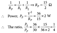
Question 60.
An electric lamp of resistance 20 Ω and a conductor of resistance 4 Ω. are connected to a 6 V battery as shown in the circuit. Calculate.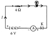
(a) the total resistance of the circuit
(b) the current through the circuit,
(c) the potential difference across the (i) electric lamp and (ii) conductor, and
(d) power of the lamp. (Delhi 2019)
Answer:
Resistance of the lamp = 20 Ω
External resistance = 4 Ω
(a) As both the lamp and external resistance are connected in series, therefore the total resistance,
R = 20 + 4 = 24 Ω
(b) Current, I =
(c) (i) Potential difference across the electric lamp
=
(ii) Potential difference across conductor
=
(d) Power of the lamp
= (current)² × resistance of lamp
= (0.25)² × 20 = 1.25 W
Question 61.
Compare the power used in 2 Ω. resistor in each of the following circuits. (AI 2019)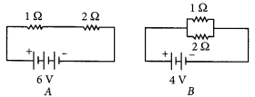
Answer:
In circuit A,
Total resistance, R = l + 2 = 3Ω
Voltage across 2 Ω =
∴ Power used in 2 Ω resistor,
p =
In circuit B, Voltage across both the resistance is same i.e. 4 V and both are connected in parallel combination.
∴ Power used in 2 Ω resistor =
∴ Power used in 2 Ω resistor in each case is same i.e. 8 W.
Question 62.
A bulb is rated 40 W; 220 V. Find the current drawn by it, when it is connected to a 220 V supply. Also find its resistance. If the given bulb is replaced by a bulb of rating 25 W; 220 V, will there be any change in the value of current and resistance? Justify your answer and determine the change. (AI 2019)
Answer:
In first case, P = 40 W, V = 220 V
Current drawn l =
Also, resistance of bulb,
R =
In second case, P = 25 W, V = 220 V
Current drawn, I =
Also, resistance of the bulb,
R =
Hence, by replacing 40 W bulb to 25 W bulb, having same source of voltage the amount of current flows decreases while resistance increases.
Question 63.
(a) How two resistors, with resistances R1 Ω and R1 Ω respectively are to be connected to a battery of emf V volts so that the electrical power consumed is minimum?
(b) In a house 3 bulbs of 100 watt each lighted for 5 hours daily, 2 fans of 50 watt each used for 10 hours daily and an electric heater of 1.00 kW is used for half an hour daily. Calculate the total energy consumed in a month of 31 days and its cost at the rate of Rs 3.60 per kWh. (Board Term I, 2017)
Answer:
(a) Power consumed is minimum when current through the circuit is minimum, so the two resistors are connected in series.
(b) Power of each bulb P1 = 100 watt
Total power of 3 bulbs, P1 = 3 × 100 = 300 watt
Energy consumed by bulbs in 1 day
E1 = P1 × t = 300 watt × 5 hours.
= 1500 Wh = 1.5 kWh
Power of each fan = 50 watt
Total power of 2 fans = 2 × 50 watt
P2 = 100 watt
Energy consumed by fans in 1 day
E2 = P2 × t = 100 watt × 10 hours
= 1000 watt hour = 1 kWh
Energy consumed by heater,
E3 = 1 kW × 1/2 h = 0.5 kWh
Total energy consumed in one day
E = E1 + E2 + E3 = (1.5 + 1 + 0.5) kWh = 3 kWh
Total energy consumed in a month of 31 days
= E × 31 = (3 × 31) kWh = 93 kWh
Cost of energy consumed = Rs (93 × 3.60) = Rs 334.80
Question 64.
(a) An electric bulb is connected to a 220 V generator. If the current drawn by the bulb is 0.50 A, find its power.
(b) An electric refrigerator rated 400 W operates 8 hours a day. Calculate the energy per day in kWh.
(c) State the difference between kilowatt and kilowatt hour. (3/5, Board Term I, 2013)
Answer:
(a) Here, V = 220 V, I = 0.50 A
Power of the bulb, P = VI = (220 × 0.5)W = 110 W
(b) Energy consumed by electric refrigerator in a day = Power x time
= 400 W × 8 h = 3200 Wh = 3.2 kWh
(c) Kilowatt is unit of power and kilowatt hour is a unit of energy.
Question 65.
(i) State one difference between kilowatt and kilowatt hour. Express 1 kWh in joules.
(ii) A bulb is rated 5V; 500 mA. Calculate the rated power and resistance of the bulb when it glows. (Board Term I, 2013)
Answer:
(i) Refer to answer 64(c).
1 kWh = 1000 W × 1 h
= 1000 W × 3600 s = 3600000 J = 3.6 × 10⁶ J
(ii) Here, V = 5 V, I = 500 mA = 0.5 A
Power rating of bulb is
P = VI = ( 5 × 0.5)W = 2.5W
Resistance of the bulb is R = V/I = (5/0.5) Ω = 10 Ω
CBSE Class 10 Science Notes Chapter 12 Electricity
Electricity: Electric current, electric circuit, voltage or electric potential, resistance and (Ohm’s law).
Electric Current: The flow of electric charge is known as Electric Current, Electric current is carried by moving electrons through a conductor.
By convention, electric current flows in the opposite direction to the movement of electrons.
Electric Circuit: Electric circuit is a continuous and closed path of electric current.
Expression of Electric Current: Electric current is denoted by the letter ‘I’. Electric current is expressed by the rate of flow of electric charges. Rate of flow means, the amount of charge flowing through a particular area in unit time.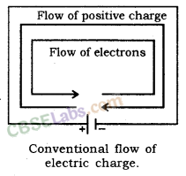
If a net electric charge (Q) flows through a cross-section of a conductor in time t, then,
Where I is electric current, Q is a net charge and t is a time in second.
S.I. Unit of Electric Charge and Current: S.I. unit of electric charge is coulomb (C).
One coulomb is nearly equal to 6 × 10¹⁸ electrons. S.I. unit of electric current is ampere (A). Ampere is the flow of electric charge through a surface at the rate of one coulomb per second. This means, if 1 coulomb of electric charge flows through a cross section for 1 second, it would be equal to 1 ampere.
Therefore, 1 A = 1 C/1 s
Small Quantity of Electric Current: Small quantity of electric current is expressed in milliampere and microampere. Milliampere is written as mA and microampere as pA.
1 mA (milliampere) = 10-3 A
1 pA (microampere) = 10-6 A
Ammeter: An apparatus to measure electric current in a circuit.,
Charge: Like mass, the charge is the fundamental property of matter. There are two types of charge
(i) Positive charge.
(ii) Negative charge.
Positive and Negative Charge: The charge acquired by a glass rod when rubbed with silk is called a positive charge and the charge acquired by an ebonite rod when rubbed with wool is called negative charge.
Properties of Electric Charge:
(i) Unlike charges attract each other and like charges repel each other.
(ii) The.force between two charges varies directly as the product of two charges and inversely as the square of the distance (r) between both charges (q1 and q2).
S.I. unit of charge is coulomb (C).
1 coulomb = 1 ampere × 1 second.
1C = 1A × 1s
Thus, the quantity of charge which flows through a circuit when one ampere of current flows through it in one second is known as a 1-coulomb charge.
Electric Potential and Potential Difference
Electric Potential: The amount of electric potential energy at a point is called electric potential.
Potential Difference: The difference in the amount of electric potential energy between two points in an electric circuit is called electric potential difference.
Electric potential difference is known as voltage, which is equal to the amount of work done to move the unit charge between two points against static electric field.
Therefore, Voltage =
Voltage or electric potential difference is denoted by V’. Therefore, V =
Where, W = Work done and Q = Charge
S.I. Unit of Electric Potential Difference (Voltage)
S.I. unit of electric potential difference is volt and denoted by ‘V’ This is named in honour of Italian Physicist Alessandro Volta.
Since joule is the unit of work and Coulomb is the unit of charge, 1 volt of electric potential difference is equal to the 1 joule of work to be done to move a charge of 1 coulomb from one point to another in an electric circuit. Therefore
1V = 1Joule/1Coulomb = 1J/1C
1V = 1JC-1
Voltmeter: An apparatus to measure the potential difference or electric potential difference between two points in an electric circuit.
Galvanometer: It is a device to detect current in an electric circuit.
Ohm’s Law: Ohm’s Law states that the potential difference between two points is directly proportional to the electric current, at a constant temperature.
This means potential difference V varies as electric current.
V ∝ I
V = RI
I =
R =
Where, R is constant for the given conductor at a given temperature and is called resistance.
Resistance: Resistance is the property of conductor which resists the flow of electric current through it.
S.I. unit of resistance is ohm. Ohm is denoted by Greek letter ‘Q’
1 Ohm: 1 ohm (Q) of resistance (R) is equal to the flow 1A of current through a conductor between two points having a potential difference equal to 1V.
This means; 1Ω =
From the expression of Ohm’s Law, it is obvious that electric current through a resistor is inversely proportional to resistance. This means electric current will decrease with an increase in resistance and vice versa. The graph of V (potential difference) versus I (electric current) is always a straight line.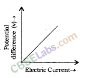
Graph of Potential Difference (V) Vs Electric Current (I)
Voltage, i.e. Potential diffrence (V) = ?
We know, from Ohm’s Law that,
R =
15 Ω =
V = 225V
Resistance: Resistance is a property of conductor due to which it resists the flow of electric current through it. A component that is used to resist the flow of electric current in a circuit is called a resistor.
In practical application, resistors are used to increase or decrease the electric current.
Variable Resistance: The component of an electric circuit which is used to regulate the current, without changing the voltage from the source, is called variable resistance.
Rheostat: This is a device which is used in a circuit to provide variable resistance.
Cause of Resistance in a Conductor: Flow of electrons in a conductor is electric current. The positive particles of conductor create hindrance to flow of electrons, because of attraction between them, this hindrance is the cause of resistance in the flow of electricity.
Factors on Which Resistance of a Conductor Depends: Resistance in a conductor depends on nature, length and area of cross section of the conductor.
(i) Nature of Material: Some materials create least hindrance and hence, are called good conductors. Silver is the best conductor of electricity. While some other materials create more hindrance in the flow of electric current, i.e. flow of electrons through them. Such materials are called bad conductors. Bad conductor are also known as insulators. Hard plastic is the one of the best insulators of electricity.
(ii) Length of Conductor: Resistance (R) is directly proportional to the length of the conductor. This means, resistance increases with increase in length of the conductor. This is the cause that long electric wires create more resistance to the electric current. Thus, Resistance (R) ∝ length of conductor (l)
or, R ∝ l …(i)
(iii) Area of Cross Section: Resistance R is inversely proportional to the area of cross section (A) of the conductor. This means R will decrease with an increase in the area of conductor and vice versa. More area of conductor facilitates the flow of electric current through more area and thus, decreases the resistance. This is the cause that thick copper wire creates less resistance to the electric current.
Thus, resistance (R) ∝ 1/Area of cross section of conductor (A)
or, R ∝
From equations (i) and (ii)
R ∝
R = ρ
Where, ρ (rho) is the proportionality constant. It is called the electrical resistivity of the material of conductor.
From equation (iii) RA = ρl ⇒ ρ =
The S.I. of Resistivity: Since, the S.I. unit of R is Q, S.I. unit of area is m2 and S.I. unit of length is m. Hence, unit of resistivity (ρ) =
Thus, S.I. unit of resistivity (ρ) is Ωm.
Resistivity: It is defined as the resistance offered by a cube of a material of side 1m when current flows perpendicular to its opposite faces. It’s S.I. unit is ohm-meter (Ωm).
Resistivity, ρ =
Resistivity is also known as specific resistance.
Resistivity depends on the nature of the material of the conductor.
Materials having a resistivity in the range of 10-8 Ωm to 10-6 Ωm are considered as very good conductors. Silver has resistivity equal to 1.60 × 10⁻⁸ Ωm and copper has resistivity equal to 1.62 × 10⁻⁸ Ωm.
Rubber and glass are very good insulators. They have a resistivity in the order of 10-12 Ωm to 10-8 Ωm.
The resistivity of materials varies with temperature.
Combination of resistors (Series and Parallel combination), the heating effect of electric current and electric power.
Combination of Resistors
(i) Series combination
(ii) Parallel combination.
1. Resistors in Series: When resistors are joined from end to end, it is called in series. In this case, the total resistance of the system is equal to the sum of the resistance of all the resistors in the system.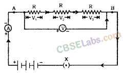
Let, three resistors R1, R2, and R3 get connected in series.
Potential difference across A and B = V
Potential difference across R1, R2 and R3 = V1, V2 and V3
Current flowing through the combination = I
We, know that
V= V1 + V2 + V3 …. (i)
According to Ohm’s Law :
V1 = IR1, V2 = IR2 and V3 = IR3 ….. (ii)
Let, total resistance = Rs
Then, V = IRs …(iii)
From equations (i) and (ii) and (iii)
IRs = IR1 + IR2 + IR3
Rs = R1 + R2 + R3
When the resistors are connected in series, the current flowing through each resistor is the same and is equal to the total current.
2. Resistors in Parallel: When resistors are joined in parallel, the reciprocal of the total resistance of the system is equal to the sum of reciprocal of the resistance of resistors.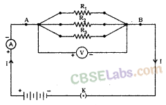
Let three resistors R1, R2 and R3 connected in parallel.
Potential difference across point A and B = V
Total current flowing between point A and B = I
Currents flowing through resistors R1, R2 and R3 = I1, I2 and I3 respectively.
We, know that,
I = I1 + I2 + I3 …….(i)
Since, the potential difference across R1, R2, and R3 is the same = V
According to Ohm’s Law,
In parallel combination, the potential difference across each resistor is the same and is equal to the total potential difference.
The total current through the circuit can be calculated by adding the electric current through individual resistors.
Itotal = 6A + 48A + 30A + 12A + 24A = 120A
Heating Effect of Electric Current: When electric current is supplied to a purely resistive conductor, the energy of electric current is dissipated entirely in the form of heat and as a result, resistor gets heated. The heating of resistor because of dissipation of electrical energy is commonly known as Heating Effect of Electric Current. Some examples are as follows : When electric energy is supplied to an electric bulb, the filament gets heated because of which, it gives light. The heating of electric bulb happens because of heating effect of electric current.
Cause of Heating Effect of Electric Current: Electric current generates heat to overcome the resistance offered by the conductor through which it passes. Higher the resistance, the electric current will generate higher amount of heat. Thus, generation of heat by electric current while passing through a conductor is an inevitable consequence. This heating effect is used in many appliances, such as electric iron, electric heater, electric geyser, etc.
Joule’s Law Of Heating: Let, an electric current, I is flowing through a resistor having resistance = R.
The potential difference through the resistor is = V.
The charge, Q flows through the circuit for the time, t
Thus, work done in moving of charge (Q) of potential difference (V),
W = V × Q
Since this charge, Q flows through the circuit for time t
Therefore, power input (P) to the circuit can be given by the following equation :
P =
P = V ×
We know, electric current, I =
Substituting
P = VI …(ii)
i.e., P = VI
Since, the electric energy is supplied for time ?, thus, after multiplying both sides of equation (ii) by time t, we get,
P × t = VI × t = VIt ……(iii)
i.e., P = VIt
Thus, for steady current I, the heat produced (H) in time t is equal to VIt
H = VIt i.e., H = VIt
We know, according to Ohm’s Law,
V = IR
By substituting this value of V in equation (iii), we get,
H = IR × It
H = I2Rt ……(iv)
The expression (iv) is known as Joule’s Law of Heating, which states that heat produced in a resistor is directly proportional to the square of current given to the resistor, directly proportional to the resistance for a given current and directly proportional to the time for which the current is flowing through the resistor.
Electric Bulb: In an electric bulb, the filament of bulb gives light because of the heating effect of electricity. The filament of bulb is generally, made of tungsten metal, having melting point equal to 3380°C.
Electric Iron: The element of electric iron is made of alloys having high melting poir^ Electric heater and geyser work on the same mechanism.
Electric Fuse: Electric fuse is used to protect the electric appliances from high voltage if any. Electric fuse is made of metal or alloy of metals, such as aluminum, copper, iron, lead, etc. In the case of flow of higher voltage than specified, fuse wire melts and protect the electric appliances.
Fuse of 1A, 2A, 3A, 5A, 10A, etc., used for domestic purpose.
Suppose, if an electric heater consumes 1000W at 220 V.
Then electric current in circuit
I =
I =
Thus, in this case of 5A should be used to protect the electric heater in the flow of higher voltage.
Electric Power
S.I. unit of electric power is watt (W).
1W = 1 volt × 1 ampere = 1V × 1A
I kilowatt or 1kW = 1000 W
Consumption of electricity (electric energy) is generally measured in kilowatt.
Unit of electric energy is kilowatt-hour (kWh).
1 kWh = 1000 watt × 1 hour = 1 unit = 1000 W × 3600 s
1 kWh = 3.6 x 10⁶ watt second = 3.6 × 10⁶ J
Conductor: The material which can allow the flow of electrons through itself is called the conductor. It has a large number of free electrons. It offers low opposition in the flow of current.
Insulator: The material which does not allow the flow of electrons through itself is called insulator. It has less or no free electrons. It offers high opposition in the flow of current.
Electric Current: The amount of flow charge through any cross-sectional area of a conductor in unity time is called Electric Current.
It is represented by ‘I’
I =
Unit of Electric Current: It is CS-1 (coulomb per second) or Ampere (A). Electric Current is a scalar quantity. It is measured by an ammeter.
Direction: The direction of conventional current (or practical current) is opposite to the flow of electrons.
Electric potential: Electric Potential at any point in the electric field is defined as the amount of work done to bring the unit positive charge from infinity (from outside the electric field) to that point.
V =
VAB = VA – VB =
Electric Potential difference is measured by a voltmeter.
Ohm’s Law: According to this law “Under the constant physical condition the potential difference across the conductor is directly proportional to the current flowing through the conductor.”
V ∝ I
V = IR …[Where R is proportionality constant called resistance of conductor]
⇒ I =
R depends upon nature, geometry and physical condition of the conductor.
The heat generated by electric current: The potential difference between two points in an electrical field is equal to the work done in moving a unit charge from one point to another.
Then, work is done, W = VQ and Q = I × t
W = V × I × t
From Ohm’s Law, we know that
V = IR
W = IR × I × t = I2.Rt
Since heat produced by the electric current is equal to work done, W
H = W
⇒ H (heat) = I2Rt Joule.
Resistance: Ratio of the applied voltage to the current flowing in the conductor is called resistance of the conductor.
⇒ R =
S.I. Unit of resistance is VA-1 or ohm (Ω).
Resistance is the opposition offered by the conductor in the flow of current.
Practically it is
R ∝ L (L is the length of a conductor)
R ∝ 1/A (A is the area of a conductor)
So, R ∝ L/A
R = ρL/A …[Where p is proportionality constant called specific resistance of conductor
It only depend upon nature (material) and temperature of conductor.
Specific resistance or Resistivity = ρ = RA /L
It’s S.I. Unit is Qm
Combination of resistance:
- In this combination the current across every component is same but potential across every component is different.
- If resistance R1, R2 and R3 are connected in series with a battery of Potential V, then equivalence resistance of the combination
R = R1 + R2 + R3
The parallel combination of resistance:
- In this combination the current across every component is different. But potential across every component is the same.
- If resistance R1, R2 and R3 are connected in parallel with a battery of Potential V, then equivalence resistance of combination
1R=1R1+1R2+1R3
Electric Energy is amount of work done to maintain the continuous flow of electric current in the circuit.
Its S.I. unit is joule (J).
Electric power (P): The electric work done per unit time is called electric power.
Electric Power =
or P =
Electric power is also defined as the electric energy consumed per unit time.
P =
S.I. unit of electric power is Watt. When one joule of energy is used for one second, electric power is equal to one watt.
Derivation of formula for electric power:
We know that electric work done, W = V × I × t or P =
P = VI
Electric power in watts = Volts × ampere
Also V = IR …[According to Ohm’s Law]
So P = IR × I
P = I2R
We know that I =
P = (
The maximum value of electric current that can pass through an electric appliance without damaging electric appliance is called current rating of electric appliance.
NCERT Exemplar Class 10 Science Chapter 12 Electricity
Shod Answer Type Questions
1.Three 2 Ω resistors, A, B and C are connected as shown in figure. Each of them dissipates energy and can withstand a maximum power of 18 W without melting. Find the maximum current that can flow through the three resistors.
Answer.
Here, P = 18 W
Since A is in series with the parallel combination of B and C. So, it carries maximum current.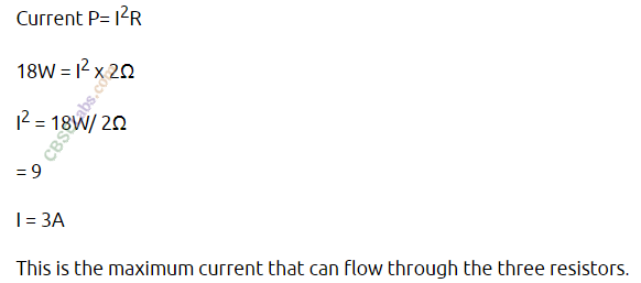
Let IB and Ic be the current flowing through B and C respectively. As they are in parallel, potential difference across them will be same, so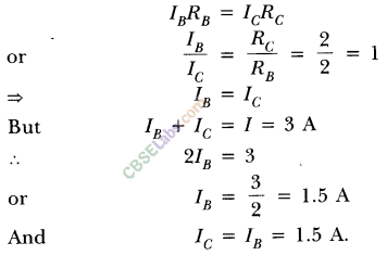
2.Should the resistance of an ammeter be low or high? Give reason.
Answer.The resistance of an ammeter should be low so that it will not disturb the magnitude of current flowing through the circuit when connected in series in a circuit.
3.How does use of a fuse wire protect electrical appliances?
Answer. The fuse wire is always connected in series with the live wire or electrical devices. If the flow of current exceeds the specified preset value due to some reason, the heat produced melts it and disconnects the circuit or the device from the mains. In this way, fuse wire protects the electrical appliances.
4.What is electrical resistivity? In a series electrical circuit comprising a resistor made up of a metallic wire, the ammeter reads 5 A. The reading of the ammeter decreases to half when the length of the wire is doubled. Why?
Answer. The resistance offered by a metallic wire of unit length and unit cross-sectional area is called electrical resistivity.
We know that
Hence, when the length of wire is doubled, the resistance becomes double and current decreases to half.
5.A current of 1 ampere flows in a series circuit containing an electric lamp and a conductor of 5 D when connected to a 10 V battery. Calculate the resistance of the electric lamp.
Now if a resistance of 10 Ω is connected in parallel with this series combination, what change (if any) in current flowing through 5 Ω conductor and potential difference across the lamp will take place? Give reason.
Answer. Given : In series circuit containing lamp and resistor,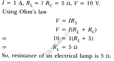
According to the given condition, circuit can be redrawn as shown.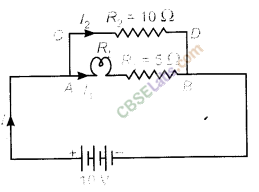
So, effective resistance of parallel combination.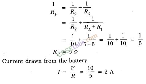
As in parallel combination, potential difference across them remains same. So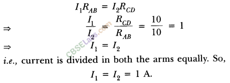
i.e., current is divided in both the arms equally. So,
l1 = l2 = lA.
Hence, there will be no change in the current through 5 n conductor.
Also there will be no change in the potential difference across the lamp as in both cases, current through the lamp remains same i.e. l A.
6.Why is parallel arrangement used in domestic wiring?
Answer.Parallel arrangement is used in domestic wiring because
- Each appliance gets the same voltage as that of the mains supply.
- If one component is switched off, others can work properly.
- Fault in any branch of the circuit can be easily identified.
7.B1 B2 and B3 are three identical bulbs connected as shown in figure. When all the three bulbs glow, a current of 3A is recorded by the ammeter A
Answer.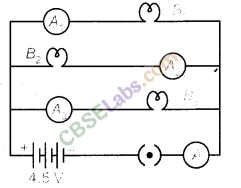
- What happens to the glow of the other two bulbs when the bulb B1 gets fused?
- What happens to the reading of A1, A2, A3 and A when the bulb gets fused?
- How much power is dissipated in the circuit when all the three bulbs glow together?
(i) Since B1 ,B2 and B3 are in parallel, the potential difference across each of them will remain same. So when the bulb Bx gets fused,B1 ,B2 and B3 have the same potential and continues with the same energy dissipated per second, i.e. they will glow continuously as they were glowing before.
(ii) Resistance of the parallel combination when all the three bulbs are glowing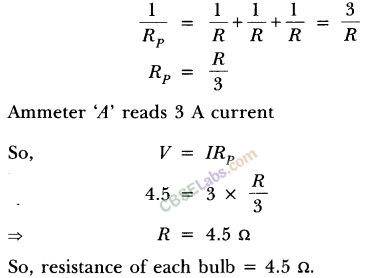
Now when bulb B2 gets fused, the equivalent resistance of parallel combination
of B1 and B3 is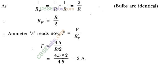
Since resistance of each arm is same and p.d. is also same, current divides them equally. So lA current will pass through each bulb Bl and By
Therefore, ammeter A1 and A3 reads l Acurrent while A2 will read zero and ammeter A read 2 A current.
(iii) In parallel, total power consumed
Peq =P1 + P2 + P3
So, when all the three bulbs glow together
Long Answer Type Questions
8. Three incandescent bulbs of 100 W each are connected in series in an electric circuit. In another circuit, another set of three bulbs of the same wattage are connected in parallel to the same source.
(а) Will the bulb in the two circuits glow with the same brightness? Justify your answer.
(b) Now let one bulb in both the circuits get fused. Will the rest of the bulbs continue to glow in each circuit? Give reason.
Answer. For three identical bulbs,
In series, Rs = 3R
In parallel, Rp = R/3
(a) The bulbs in the two circuits will not glow equally bright as the current through them is not the same.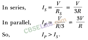
(b) As one bulb fuses, the other bulbs in the series circuit will not glow because the circuit becomes an open circuit. While the rest of bulbs in parallel circuit will continue to glow without getting disturbed because in parallel combination, current gets additional paths to flow.
9.Find out the following in the electric circuit given in figure: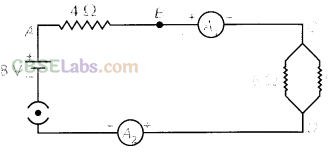
(a) Effective resistance of two 8 Ω resistors in the combination,
(b) Current flowing through 4 Ω resistor,
(c) Potential difference across 4 Ω resistance,
(d) Power dissipated in 4 Ω resistor, and
(e) Difference in ammeter readings, if any.
Answer.
(a) Effective resistance, the two 8 Ω resistors in parallel,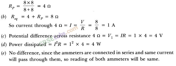
.png)
.png)